Eureka AIR delivers breakthrough ideas for toughest innovation challenges, trusted by R&D personnel around the world.

Anti-theft electromagnetic lock device for rail transit platform door

A technology for rail transit and platform doors, applied in the field of electromagnetic locks, which can solve the problems of anti-theft electromagnetic locks that cannot operate normally, lack of emergency starting devices, and reduce the practical performance of equipment, etc., to achieve convenient maintenance and replacement, simple structure, and short disassembly time Effect

Pending Publication Date: 2021-02-23
常州市东方浩友科技有限公司
View PDF0 Cites 1 Cited by
  • Summary
  • Abstract
  • Description
  • Claims
  • Application Information

AI Technical Summary

Problems solved by technology

[0004] The purpose of the present invention is to solve the existing anti-theft electromagnetic locks. When encountering a temporary power failure, the anti-theft electromagnetic locks cannot operate normally, which reduces the practical performance of the equipment, and most of the existing anti-theft electromagnetic locks do not have The emergency start device prevents passengers from leaving, which increases the rate of accidents, and proposes a rail transit platform door anti-theft electromagnetic lock device

Method used


Image

  • Anti-theft electromagnetic lock device for rail transit platform door
  • Anti-theft electromagnetic lock device for rail transit platform door
  • Anti-theft electromagnetic lock device for rail transit platform door

Examples


Embodiment Construction

[0021] The preferred embodiments of the present invention will be described below in conjunction with the accompanying drawings. It should be understood that the preferred embodiments described here are only used to illustrate and explain the present invention, and are not intended to limit the present invention.

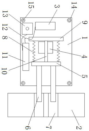
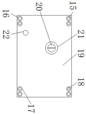
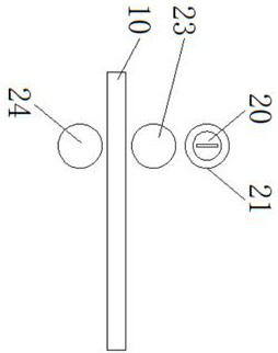
[0022] Such as Figure 1-Figure 3 As shown, a rail transit platform door anti-theft electromagnetic lock device includes an anti-theft lock body 1, a lock body 2, an electromagnetic controller 3, a first magnet 4, a second magnet 5, a fixed column 6, a lock groove 7, and a spring 8 , fixed bar 9, gear bar 10, backup power group 11, wire 12, power controller 13, fixed ring 14, cylinder 15, first gear block 16, second gear block 17, rotating handle 18, lock case 19, lock Core 20, rotating block 21, control button 22, driving gear block 23 and driven gear block 24, the inside of anti-theft lock body 1 is fixedly equipped with electromagnetic controller 3, and the right...


PUM


Abstract

The invention discloses an anti-theft electromagnetic lock device for a rail transit platform door, and relates to the technical field of electromagnetic locks. The anti-theft electromagnetic lock device for the rail transit platform door comprises an anti-theft lock body, wherein an electromagnetic controller is fixedly installed in the anti-theft lock body; and the right side of the electromagnetic controller is fixedly connected with a first magnet. According to the anti-theft electromagnetic lock device for the rail transit platform door provided by the invention, a control button is pressed down, the electromagnetic controller is started and drives a fixed column to move through the first magnet, a second magnet, a spring and a fixed strip (the fixed column is moved out of a lock groove), then the electromagnetic controller is disconnected, and the fixed column is reset through the spring and the second magnet (the fixed column is moved into a sliding groove), so that the anti-theft electromagnetic lock is conveniently opened and closed; an opening and closing mechanism is stable in operation, simple in structure and convenient to use; and when temporary power failure occurs,the opening and closing work of the anti-theft electromagnetic lock can be achieved through a standby power source set, so that a high practical performance is achieved.

Description

technical field [0001] The invention relates to the technical field of electromagnetic locks, in particular to an anti-theft electromagnetic lock device for rail transit platform doors. Background technique [0002] With the development of science and technology and the progress of the times, the transportation is more and more developed, and the subway is becoming more and more popular in many cities. All new urban rail transit projects in the country are designed and installed with anti-theft electromagnetic lock devices. The design of electromagnetic locks and electromagnets Similarly, it uses the principle of electromagnetism. When the current passes through the silicon steel sheet, the electromagnetic lock will generate a strong suction force to tightly absorb the adsorption iron plate to achieve the effect of locking the door. [0003] Existing anti-theft electromagnetic locks, when encountering a temporary power failure, the anti-theft electromagnetic locks cannot ope...

Claims


Application Information

Patent Timeline
Patent Type & Authority Applications(China)
IPC IPC(8): E05B47/02E05B9/00
CPCE05B9/00E05B47/0002E05B47/026E05B2047/0087
Inventor 杜一鸣侯东东侯淑丽
Owner 常州市东方浩友科技有限公司
Why Eureka
Eureka Blog
Learn More