Fuel cell separator and single fuel cell

A fuel cell and single cell technology, applied in the direction of fuel cells, circuits, electrical components, etc., to achieve the effect of reducing the reduction of power generation performance

Pending Publication Date: 2021-02-23
TOYOTA JIDOSHA KK
View PDF13 Cites 0 Cited by
  • Summary
  • Abstract
  • Description
  • Claims
  • Application Information

AI Technical Summary

Problems solved by technology

[0012] However, it is also required to suppress the decrease in power generation efficiency and the generation of flooding of the single cells for fuel cells

Method used


Image

  • Fuel cell separator and single fuel cell
  • Fuel cell separator and single fuel cell
  • Fuel cell separator and single fuel cell

Examples


Embodiment Construction

[0025] Hereinafter, embodiments of the present disclosure will be described in detail. In addition, this indication is not limited to the following embodiment, Various deformation|transformation can be implemented within the range of the main point which was disclosed.

[0026] Separator for fuel cells

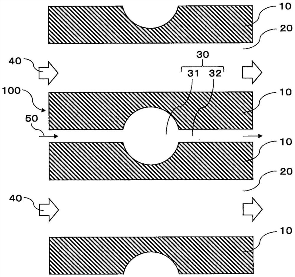
[0027] The fuel cell separator of the present disclosure has a plurality of gas flow paths separated from each other by ribs, on the surface of the gas flow path, on the surface of the ribs, there are liquid water flow paths separated from the gas flow path along the gas flow path, In addition, the liquid water flow path has an expansion area, and the cross-sectional area of ​​the expansion area of ​​the liquid water flow path in the direction perpendicular to the flow direction is larger than the cross-sectional area of ​​other regions of the liquid water flow path in the direction perpendicular to the flow direction.

[0028] The fuel cell separator of the present disclosur...


PUM


Abstract

A fuel cell separator and a single fuel cell are disclosed. The fuel cell separator includes ribs. The fuel cell separator has a plurality of gas flow paths separated from each other by the ribs. Thefuel cell separator has, on a surface of the ribs on the gas flow path side, a liquid water flow path provided separately from the gas flow paths along the gas flow paths. The liquid water flow path has an expanded region in which a cross-sectional area of the liquid water flow path in a direction perpendicular to a flow direction of the liquid water flow path is larger than a cross-sectional areaof the liquid water flow path in the direction perpendicular to the flow direction in a remaining region of the liquid water flow path.

Description

technical field [0001] The present disclosure relates to a separator for a fuel cell and a single cell for a fuel cell. Background technique [0002] As a structure of a single cell for a fuel cell, a structure in which a membrane electrode assembly, a gas diffusion layer, and a separator are laminated is known. Here, the separator has a gas flow path through which the reaction gas, ie, the cathode gas or the anode gas, flows into the single fuel cell. [0003] In the single cell for fuel cell having the above-mentioned structure, liquid water such as produced water formed by the cell reaction enters the gas flow path, thereby clogging the gas flow path, whereby gas flows into the single cell for fuel cell. Reduced efficiency, reduced power generation efficiency, and / or potential for flooding, etc. [0004] In response to such a possibility, in order to efficiently discharge liquid water from the inside of a fuel cell cell, optimization of the shape of the gas flow path, t...

Claims


Application Information

Patent Timeline
Patent Type & Authority Applications(China)
IPC IPC(8): H01M8/0265H01M8/0258H01M8/1007
CPCH01M8/0265H01M8/0258H01M8/1007Y02E60/50H01M2008/1095H01M8/0267
Inventor 李桦
Owner TOYOTA JIDOSHA KK
Why Eureka
Try Eureka