Inflatable castle capable of being folded automatically
A castle and automatic technology, applied in the field of amusement facilities, can solve the problems of inconvenient use, high labor intensity and low work efficiency of bouncy castles, and achieve the effect of avoiding manual methods, low labor intensity and ensuring reliability.
- Summary
- Abstract
- Description
- Claims
- Application Information
AI Technical Summary
Problems solved by technology
Method used
Image
Examples
Embodiment 1
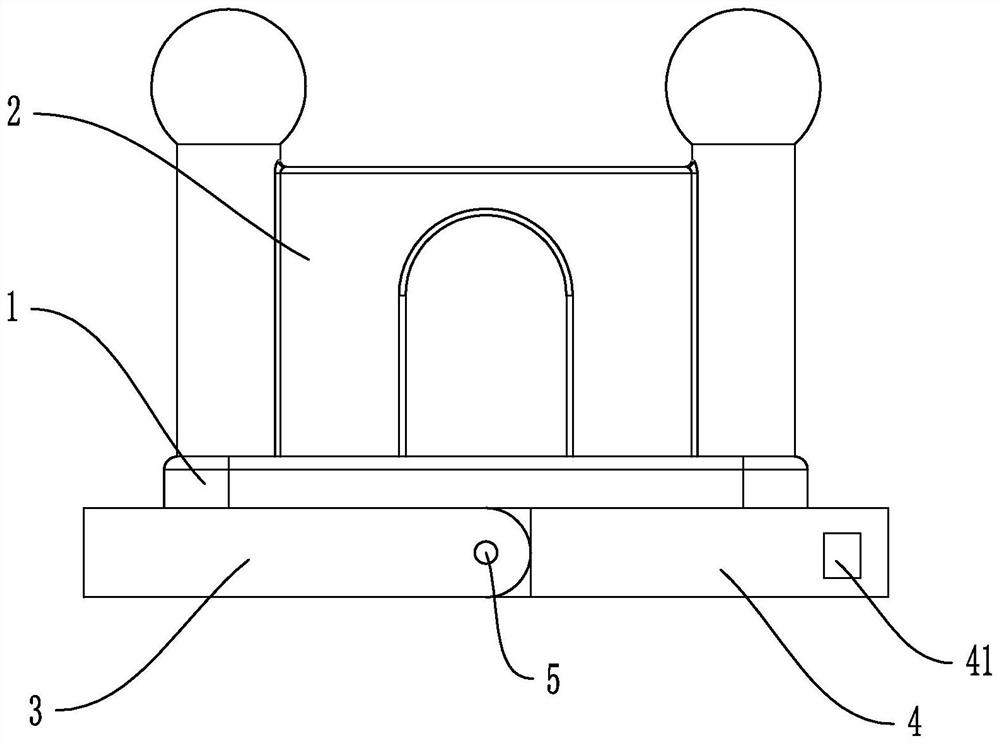
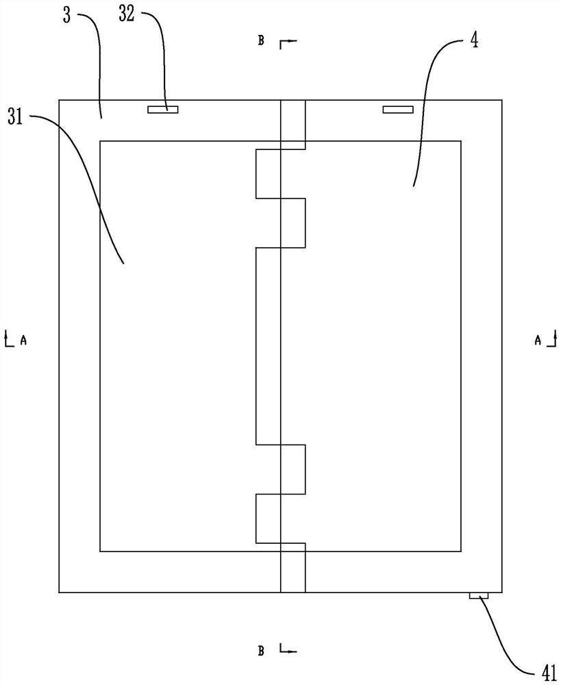
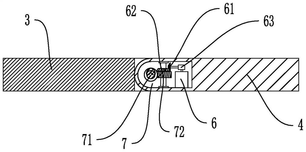
[0030] Embodiment 1, this embodiment discloses an automatically retractable bouncy castle, such as Figures 1 to 4 As shown, it includes an inflatable base 1 and a play part 2 located on the inflatable base 1. The underside of the inflatable base 1 is provided with a first folding base 3 and a second folding base 4 that are compatible with it. The first folding base One end of the base 3 is hingedly connected with the second folding base 4 by setting the hinge 5, and the other end is detachably connected with the second folding base 4 through a buckle mode. When the bouncy castle is in use, the first folding The base 3 and the second folding base 4 are mutually unfolded. When not in use, the first folding base 3 and the second folding base 4 are folded and folded together. The first folding base 3 and the second folding base 4 A retractable device is provided at the joint, and the retractable device includes a driving motor 6 and a rotating assembly 7 that is compatible with t...
Embodiment 2
[0035] Embodiment 2, the difference between this embodiment and Embodiment 1 is that, if Figures 5 to 7 As shown, the rotating assembly 7 includes a rotating shaft 73 and at least one arc-shaped push rod 74 adapted to the rotating shaft 73. Both ends of the rotating shaft 73 are movably connected with the second folding base 4, and rotate The shaft 73 is provided with a rotating gear 732 which is fixedly connected with it. One side of the rotating gear 732 is provided with a driven gear 733 connected with the first folding base 3 . The internal gear groove 741 that the driven gear 733 is compatible with, the center of circle of the arc-shaped push rod 74 and the center of circle of the rotating shaft 73 are on the same center line, and one end of the arc-shaped push rod 74 is installed on the first folding base 3 , and the other One end is fixedly connected to the second folding base 4; the driving motor drives the rotating gear 732 through the rotating shaft 73 and then driv...
PUM
 Abstract
Description
Claims
Application Information
 - R&D Engineer
- R&D Manager
- IP Professional
- Industry Leading Data Capabilities
- Powerful AI technology
- Patent DNA Extraction
Browse by: Latest US Patents, China's latest patents, Technical Efficacy Thesaurus, Application Domain, Technology Topic, Popular Technical Reports.
© 2024 PatSnap. All rights reserved.Legal|Privacy policy|Modern Slavery Act Transparency Statement|Sitemap|About US| Contact US: help@patsnap.com


