Supercharge Your Innovation With Domain-Expert AI Agents!

Channel steel cutting device

A technology of cutting device and channel steel, applied in the direction of shearing device, feeding device, shearing machine equipment, etc., which can solve the problems of falling off of processed parts and inability to automatically discharge parts, etc.

Active Publication Date: 2021-02-26
湖北立晋钢铁集团有限公司
View PDF12 Cites 0 Cited by
  • Summary
  • Abstract
  • Description
  • Claims
  • Application Information

AI Technical Summary

Problems solved by technology

[0005] The purpose of the present invention is to provide a channel steel cutting device to solve the problem of the falling off of the workpiece and the inability to automatically discharge the parts proposed in the background technology

Method used


Image

  • Channel steel cutting device
  • Channel steel cutting device
  • Channel steel cutting device

Examples


Embodiment Construction

[0022] The following will clearly and completely describe the technical solutions in the embodiments of the present invention with reference to the accompanying drawings in the embodiments of the present invention. Obviously, the described embodiments are only some, not all, embodiments of the present invention. Based on the embodiments of the present invention, all other embodiments obtained by persons of ordinary skill in the art without making creative efforts belong to the protection scope of the present invention.

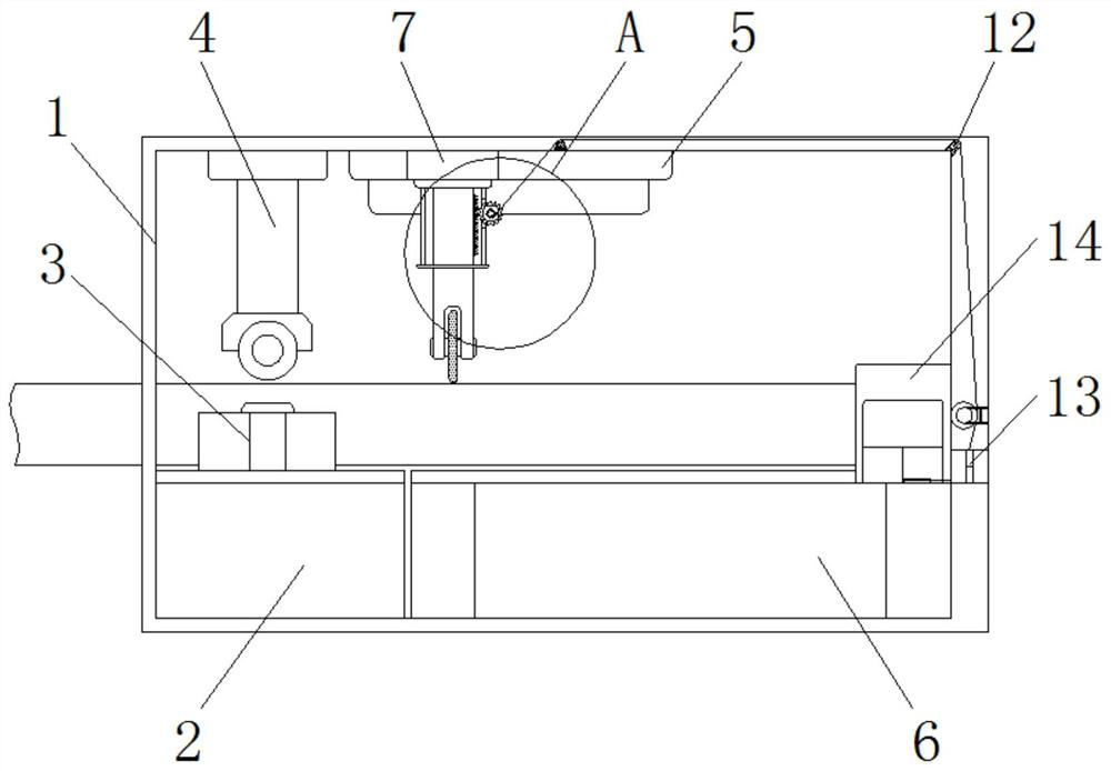
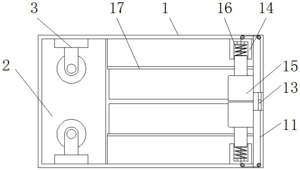
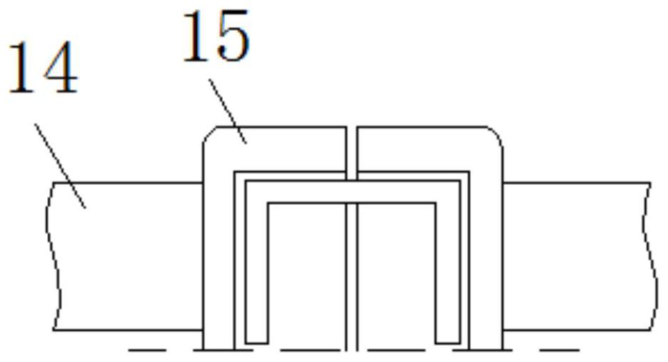
[0023] see Figure 1-6 , the present invention provides a technical solution: a channel steel cutting device, including a base body 1, a support table 2, a fixed rod 3, an extrusion rod 4, a fixed block 5, an accommodating block 6, an electric push rod 7, and a cutting blade 8 , rack 9, gear 10, traction rope 11, fixed pulley 12, guide pipe 13, telescopic rod 14, limit block 15, spring 16, telescopic plate 17, pad 18, card slot 19, motor 20, conveyor belt 21, ...


PUM


Abstract

The invention discloses a channel steel cutting device. The channel steel cutting device comprises a base body, a fixing rod, a traction rope, limiting blocks and a cushion block, a supporting table is arranged in the interior of the base body, the fixing rod is fixedly installed at the upper end of the supporting table, an extrusion rod is arranged at the upper end of the inner surface of the base body, the fixing block is installed at the upper end of the inner surface of the base body, and a containing block is arranged at the lower end of the inner surface of the base body, an electric push rod is installed in the interior of the fixing block, a cutting blade is fixedly installed at the output end of the electric push rod, a rack is fixedly installed on the outer side of the electric push rod, the outer side of the rack is connected with a gear, and the inner side of the gear is in shaft connection with the traction rope. According to the channel steel cutting device, the limitingblocks are arranged, after limiting and fixing are carried out on the inlet end of a machined part through the fixing rod and the extrusion rod, limiting and fixing are carried out on the head end ofthe machined part under the action of the two sets of limiting blocks, a telescopic rod and a spring, and therefore the phenomenon that the machined part falls off due to cutting vibration in the machining and cutting process is avoided.

Description

technical field [0001] The invention relates to the technical field of channel steel processing, in particular to a channel steel cutting device. Background technique [0002] Steel is the most used metal material. It has high strength, good mechanical properties, and low cost. It is suitable for large-scale production and is widely used in various fields of social production and life. The channel steel in steel has a grooved cross section. Type steel is often used in construction and mechanical fields, and the channel steel needs to be cut before use to obtain the required length, but the existing cutting devices still have certain defects, such as; [0003] When the existing cutting device is cutting the channel steel, due to the vibration of the cutting force, the workpiece is shaken and unstable, which may easily cause the workpiece to fall off, and after the cutting is completed, the workpiece needs to be disassembled to be taken out, which is not convenient Automatica...

Claims


Application Information

Patent Timeline
IPC IPC(8): B23D19/08B23Q5/22
CPCB23D19/08B23Q5/22
Inventor 曹立晋宋磊
Owner 湖北立晋钢铁集团有限公司
Features
  • R&D
  • Intellectual Property
  • Life Sciences
  • Materials
  • Tech Scout
  • Unparalleled Data Quality
  • Higher Quality Content
  • 60% Fewer Hallucinations
Learn More