[0028]The present invention will be described in further detail below with reference to the drawings and specific embodiments. It should be noted here that the technical features involved in the various embodiments of the present invention described below can be combined with each other as long as they do not conflict with each other.
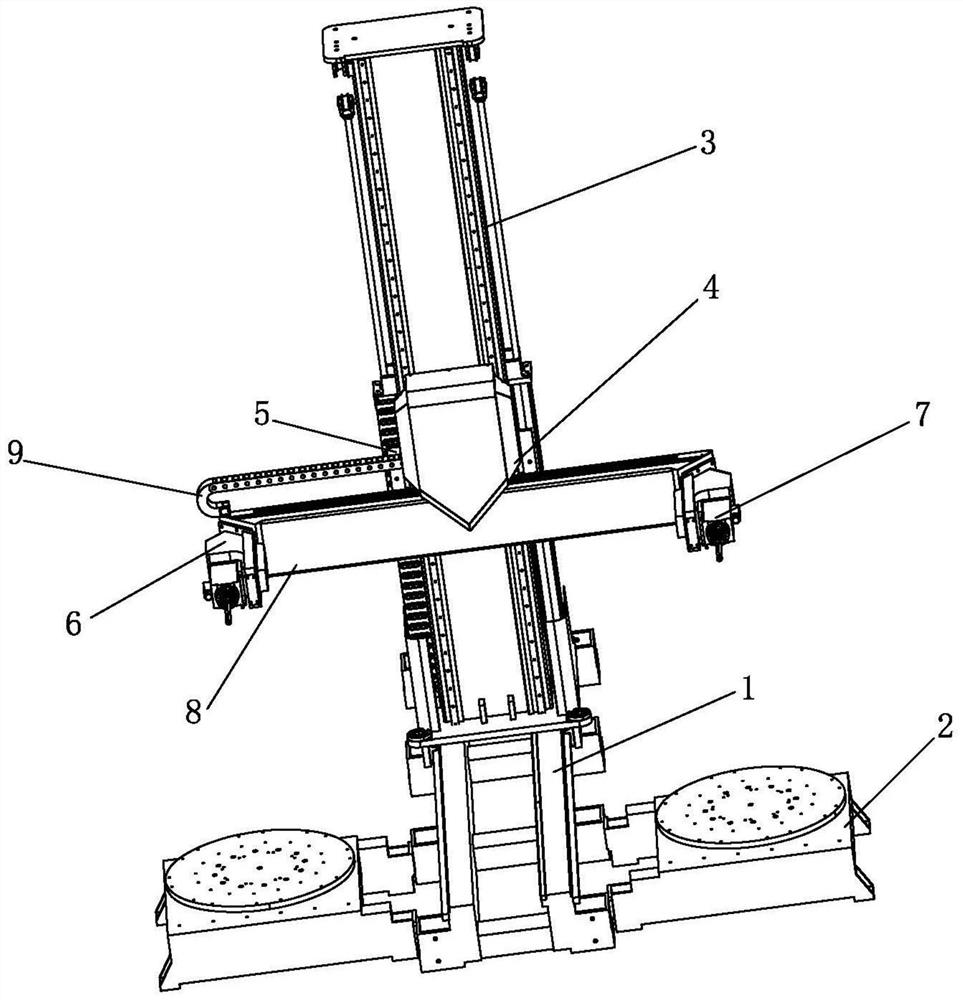
[0029]In order to solve the problems of the existing relief engraving machine occupying a large space, the engraving function is single, and the engraving efficiency is low, this application discloses a double-head engraving machine, such asfigure 1 ,figure 2 ,image 3 ,Figure 4 ,Figure 5 ,Figure 6 Shown, including:
[0030]The frame 1, the frame 1 is provided with two symmetrical bases 2 and lifting brackets 3, and the frame 1, the base 2 and the lifting brackets 3 are made of stainless steel. The lifting bracket 3 and the frame 1 are movably connected, the lifting bracket 3 is provided with an engraving device 4, the engraving device 4 is movably connected with the lifting bracket 3, and the engraving device 4 includes a fixed plate 5 and The engraving assembly 6 movably connected with the fixed plate 5, the engraving assembly 6 includes a connecting shaft 8 and an engraving head 7 arranged at both ends of the connecting shaft 8. The engraving head 7 includes an engraving tool 71, an engraving base plate 72 and a rotating motor 73. The engraving base plate 72 is fixed on the connecting shaft 8, the engraving tool 71 is provided with a rotating shaft 74, and the rotating shaft 74 is connected to the rotating motor 73 through a conveyor belt. After the rotating motor 73 is rotated, the force is transmitted to the rotating shaft 74 through the conveyor belt, and the rotating shaft 74 will rotate at a specific angle, generally 90 degrees, so that the head of the engraving tool 71 is forward to the head downward. The direction of the cutter head can be adjusted to realize different relief carvings. When the head of the engraving tool 71 is down, you can engrave smaller objects and engrave downwards. When the head of the engraving tool 71 is forward, you can engrave round sculptures. It is suitable for carving large surfaces. When engraving in this application, the base 2 is used to fix the relief, the lifting bracket 3 is used to move back and forth to realize the front and back movement of the engraving device 4, the fixed plate 5 of the engraving device 4 is used to move up and down to realize the up and down movement of the engraving assembly 6, and the connecting shaft 8 is used. The left and right movement of the engraving head 7 can realize the left and right movement of the engraving head 7, thereby realizing the three-dimensional movement of the engraving head 7 and realizing the engraving at any position.
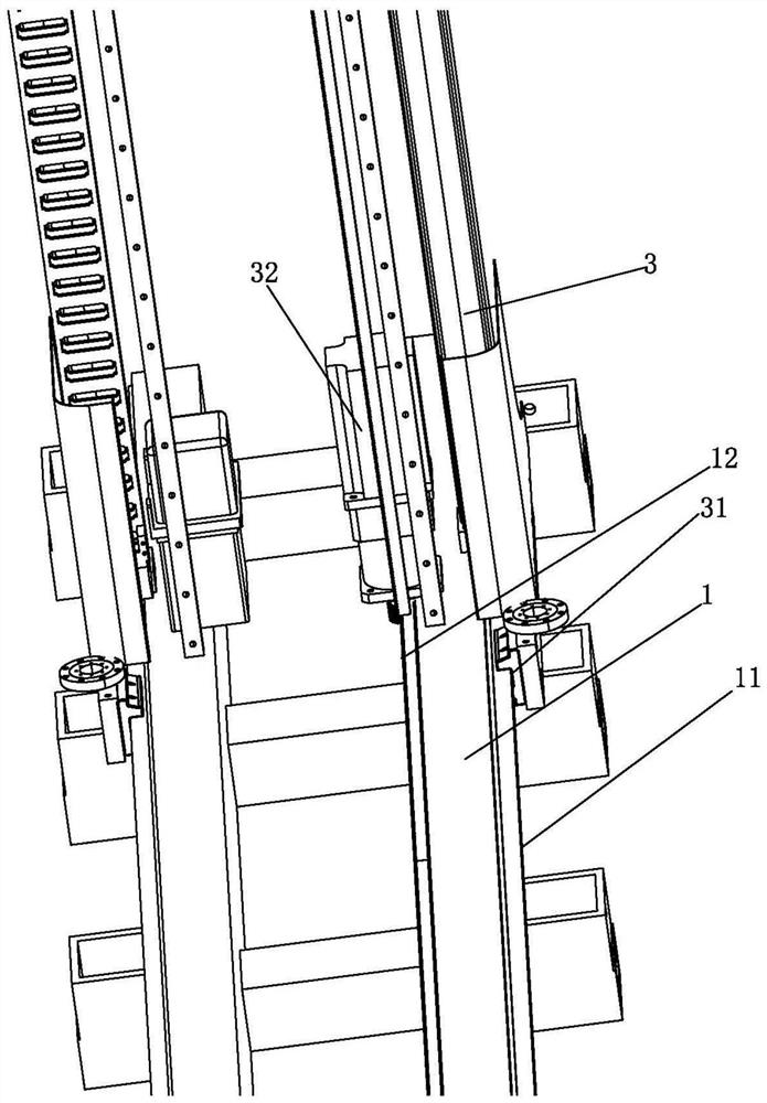
[0031]Preferably, the manner in which the lifting bracket 3 and the frame 1 are movably connected is: two sliding rails 11 are provided on the outer side of the frame 1, and the bottom end of the lifting bracket 3 is provided with a sliding groove connected to the sliding rail 11 31. A rack 12 is provided on the inner side of the frame 1, and a sliding motor 32 for driving the lifting support 3 to move forward and backward is provided in the lifting bracket 3, and the top end of the sliding motor 32 meshes with the rack 12 connection. Driven by the sliding motor 32, the top end of the sliding motor 32 is engaged with the rack 12 to move back and forth, so that the lifting bracket 3 moves along the sliding rail 11 through the sliding groove 31 to realize the front and back movement of the entire lifting bracket 3.
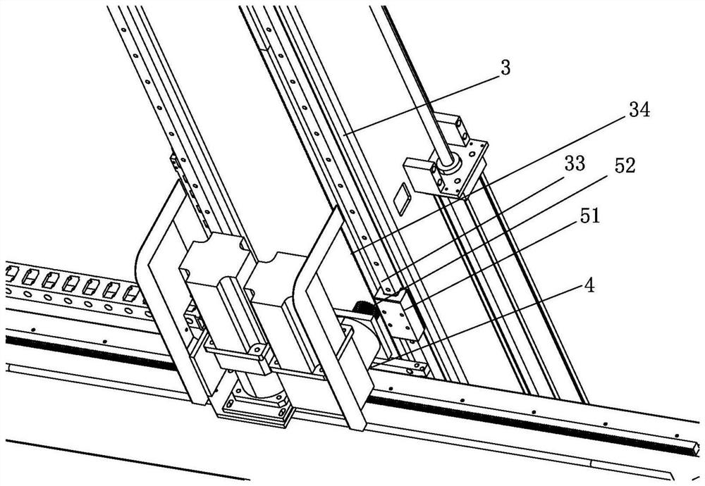
[0032]Preferably, the manner in which the engraving device 4 and the lifting bracket 3 are movably connected is: two lifting slide rails 33 are provided on the outside of the lifting bracket 3, and the fixed plate 5 is provided with a lifting slide 33 Connected lifting chute 51. A lifting rack 34 is provided on the inner side of the lifting bracket 3, a lifting motor 52 for driving the lifting bracket 3 to move up and down is provided on the fixed plate 5, and the bottom end of the lifting motor 52 is connected to the lifting rack 34. Engagement connection. After being driven by the lifting motor 52, the entire engraving device 4 is raised and lowered. The lifting motor 52 drives the entire engraving device 4 to move up and down along the lifting rack 34, and the outer side uses the lifting slide 33 and the lifting chute 51 to move up and down.
[0033]Preferably, the fixed plate 5 and the engraving assembly 6 are movably connected in a manner that: a limited drag chain 9 is arranged between the engraving device 4 and the fixed plate 5; and the fixed plate 5 is provided with a traverse slide Slot 53, the engraving device 4 is provided with a transverse sliding rail 41 matedly connected with the transverse sliding groove 53, the engraving device 4 is provided with a transverse rack 42, and the fixed plate 5 is provided with The traverse motor 54 moves left and right on the engraving device 4, and the top end of the traverse motor 54 is in meshing connection with the traverse rack 42. After being driven by the traverse motor 54, the traverse motor 54 drives the entire engraving assembly 6 to move transversely along the traverse rack 42, and the outer side of the engraving assembly 6 is coordinated with the traverse slide 53 and the traverse slide 41 to realize the entire engraving assembly 6 Move left and right to realize engraving in the left and right direction. The function of the limit drag chain 9 is to realize the limit and prevent the engraving assembly 6 from being left or the right side too much and leaving the fixed plate 5. The general limit distance is half the length of the connecting shaft 8, that is, the engraving tool on the right side. 71 can reach the middle position, or to the right, but not to the left, and the engraving component 6 can be moved left and right by using the above solution.
[0034]Preferably, the frame 1 is provided with a plurality of symmetrical clamping portions 13, and the base 2 is provided with a clamping block 21 connected to the clamping portion 13. The connection of the base 2 and the frame 1 can be realized through the cooperation of the clamping part 13 and the clamping block 21, and multiple bases 2 can be provided, and the lifting bracket 3 and the frame 1 can be movably connected to realize the engraving device 4 in multiple Engraving on each base 2 has high engraving efficiency.
[0035]Preferably, such asPicture 8As shown, the base 2 is provided with a relief support platform 22, the relief support platform 22 is provided with an extension clamping device 23, the extension clamping device 23 is composed of a plurality of telescopic rods 24, the The telescopic rod 24 is provided with a plurality of adjusting devices 25 for adjusting the length of the telescopic rod 24, the end of the telescopic rod 24 is provided with a relief fixing portion 26, and a number of fixing members 27 are provided on the relief fixing portion 26. Preferably, the telescopic rod 24 is provided with 2-5 adjusting devices 25, and the adjusting devices 25 are composed of butterfly bolts. The specific clamping method of the base 2 is to place the relief body on the extension clamping device 23 by mechanical operation, and then adjust the telescopic rod 24 through the adjusting device 25 to support the ends of the telescopic rod 24 on the surface of the relief body, and then use the adjusting device 25 For fixing, the relief body is supported and fixed by the fixing member 27 of the relief fixing portion 26 to prevent instability due to shaking. Easy to use and flexible.
[0036]Preferably, a turntable 28 is provided under the relief support platform 22. The turntable 28 can realize the rotation of the relief body and realize the engraving in multiple directions.
[0037]The method of use of the present invention is:
[0038]When the left and right engraved are exactly the same relief, place the relief on the base 2 mechanically, and after the telescopic rod 24 of the stretching and clamping device 23 is stretched to determine the size, fix the relief body on the base 2, and then set the left and right reliefs. The rotation speed and direction of each base 2 are exactly the same. Then use the lifting bracket 3 to move back and forth to realize the front and back movement of the engraving device 4, use the fixed plate 5 of the engraving device 4 to move up and down to realize the up and down movement of the engraving assembly 6, and use the left and right movement of the connecting shaft 8 to realize the left and right movement of the engraving head 7 , So as to realize the three-dimensional movement of the engraving head 7 and realize the engraving at any position, to engrave the relief body at the same time. After engraving a certain position, the turntable 28 on the left and right base 2 will rotate synchronously to realize engraving in other positions. Realize the carving of relief. When you need to adjust different engraving products, for example, you need to replace the round or square sculpture, or replace the large or small relief body, such asFigure 7 As shown, the engraving tool 71 can be driven to rotate downward by the rotating motor 73, so as to realize the engraving on the surface of the relief and on the relief, which is convenient and quick.
[0039]When the left and right engraved products are mirror images of each other, the relief is placed on the base 2 by mechanical means, and after the telescopic rod 24 of the stretching and clamping device 23 is stretched to determine the size, the relief body is fixed on the base 2 and then set The rotation speeds of the left and right bases 2 are the same, but in opposite directions. The other engraving steps are the same as the above method.
[0040]The present invention uses the base 2 to fix the relief, uses the lifting bracket 3 to move back and forth to realize the front and back movement of the engraving device 4, uses the fixed plate 5 of the engraving device 4 to move up and down to realize the up and down movement of the engraving assembly 6, and uses the left and right movement of the connecting shaft 8 The left and right movement of the engraving head 7 is realized, so as to realize the three-dimensional movement of the engraving head 7 and realize the engraving at any position. The engraving accuracy is high, and the left and right reliefs can be engraved at the same time. The engraving efficiency is high, and the engraving functions are diverse and occupy less space.
[0041]The above are only preferred embodiments of the present invention, and do not limit the technical scope of the present invention. Therefore, all changes or modifications made according to the claims and specification of the present invention shall be covered by the patent of the present invention. Within range.