Annular rotary three-dimensional space carving machine

A three-dimensional, rotary technology, applied in the field of engraving machines, can solve the problems of high-end engraving machines relying on imports, late start of engraving machine technology, and weak independent research and development capabilities.

Active Publication Date: 2021-04-30
SOUTH CHINA AGRI UNIV
View PDF3 Cites 0 Cited by
  • Summary
  • Abstract
  • Description
  • Claims
  • Application Information

AI Technical Summary

Problems solved by technology

[0002] Due to the rapid development of the manufacturing industry, traditional engraving technology is no longer suitable for the development of today's society. Various high-performance engraving machines have emerged as the times require, and have been widely demanded by the market. Weak capabilities lead to most high-end engraving machines basically relying on imports, especially in the field of high-performance three-dimensional engraving
[0003] Most of the engraving machines currently on the market are mainly three-axis, which can meet the needs of plane engraving machines. High-end equipment has five-axis engraving, which can meet space engraving, but it is expensive and only suitable for industrial fields, and the knife is subjected to radial force during engraving. and tangential force affect the precision of the engraving machine; in the field of ring space three-dimensional engraving technology, there is a blank at home and abroad

Method used


Image

  • Annular rotary three-dimensional space carving machine
  • Annular rotary three-dimensional space carving machine
  • Annular rotary three-dimensional space carving machine

Examples


Embodiment Construction

[0041] The present invention will be described in further detail below in conjunction with specific embodiments.

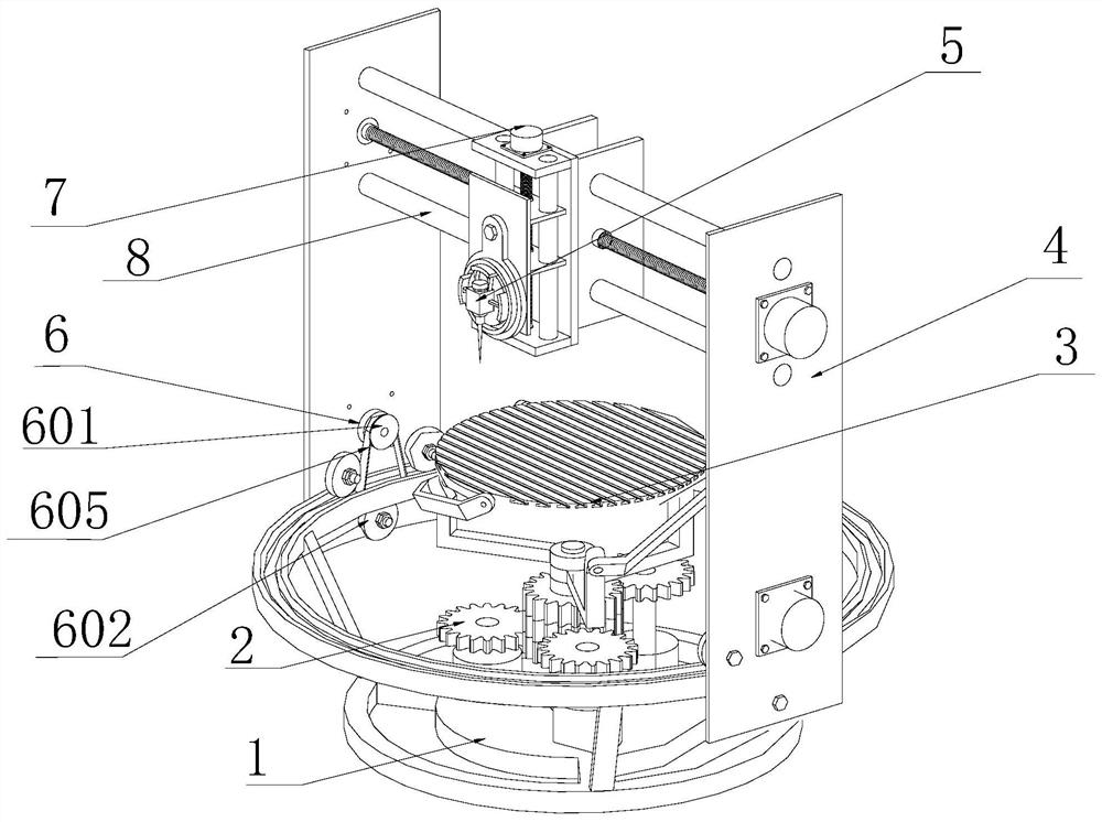
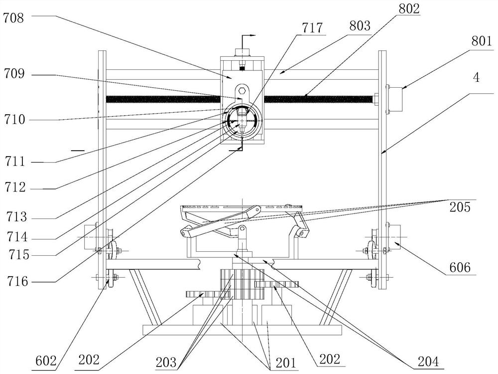
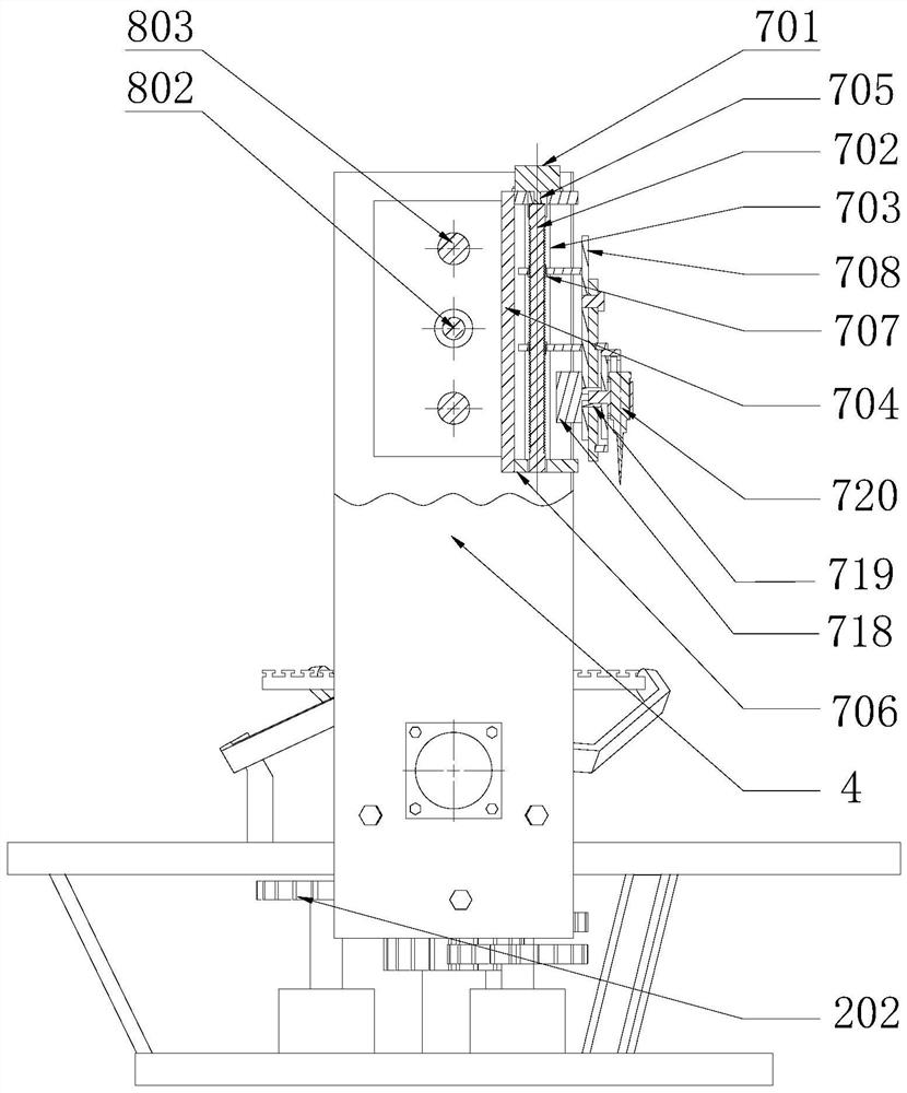
[0042] A circular rotary three-dimensional engraving machine, comprising a base 1, a parallel operation device 2, a workbench 3, an arc-shaped column 4, a cutter head assembly 5, a circular feed mechanism 6 that drives the cutter head assembly to perform circular motion in a horizontal plane, The Y-direction feed mechanism 8 that drives the cutter head assembly to move linearly in the horizontal direction, and the Z-direction feed mechanism 7 that drives the cutter head assembly to make linear motion in the vertical direction.

[0043] The workbench is connected to the base through a parallel operation device. The base is provided with a circular guide rail 101. The arc-shaped column is connected to the guide rail through a circular feed mechanism. The cutter head assembly is connected to the arc-shaped Post connection.

[0044] The circular feed mechanism includ...


PUM


Abstract

The invention discloses an annular rotary three-dimensional space carving machine. The annular rotary three-dimensional space carving machine comprises a base, a parallel operation device, a workbench, an arc-shaped stand column, a cutterhead assembly, a circumferential feeding mechanism for driving the cutterhead assembly to do circumferential motion in a horizontal plane, a Y-direction feeding mechanism for driving the cutterhead assembly to do linear motion in a horizontal direction, and a Z-direction feeding mechanism for driving the cutterhead assembly to do linear motion in a vertical direction; the workbench is connected to the base through the parallel operation device; an annular guide rail is arranged on the base; the arc-shaped stand column is connected with the guide rail through the circumferential feeding mechanism; the cutterhead assembly is connected with the arc-shaped stand column through the Y-direction feeding mechanism and the Z-direction feeding mechanism; and the circumferential feeding mechanism is a three-roller circumferential feeding mechanism. The annular rotary three-dimensional space carving machine is stable in structure and high in operation precision and belongs to the field of carving machines.

Description

technical field [0001] The invention relates to the field of engraving machines, in particular to an annular rotary three-dimensional engraving machine. Background technique [0002] Due to the rapid development of the manufacturing industry, traditional engraving technology is no longer suitable for the development of today's society. Various high-performance engraving machines have emerged as the times require, and have been widely demanded by the market. Weak capabilities have resulted in most high-end engraving machines basically relying on imports, especially in the field of high-performance three-dimensional engraving. [0003] Most of the engraving machines currently on the market are mainly three-axis, which can meet the needs of plane engraving machines. High-end equipment has five-axis engraving, which can meet space engraving, but it is expensive and only suitable for industrial fields, and the knife is subjected to radial force during engraving. And the effect o...

Claims


Application Information

Patent Timeline
Patent Type & Authority Applications(China)
IPC IPC(8): B44B1/00B44B1/06
CPCB44B1/00B44B1/06
Inventor 武涛任甲辉李珂莫王玉洁吴合槟樊秋菊胡平
Owner SOUTH CHINA AGRI UNIV
Why Eureka
Try Eureka