
Vertical engraving machine

A kind of engraving machine, vertical technology, applied in the direction of decorative art, processing models, etc., can solve the problems of engraving accuracy decline, increase machine manufacturing cost, affect engraving accuracy, etc., achieve the effect of improving engraving accuracy and saving manufacturing cost

Pending Publication Date: 2019-09-13
吴善旺
View PDF2 Cites 2 Cited by
  • Summary
  • Abstract
  • Description
  • Claims
  • Application Information

AI Technical Summary

Problems solved by technology

[0004] However, in the actual processing process, due to the large overall size and heavy weight of the columnar workpiece, when the above-mentioned revolving platform moves back and forth, the clamped workpiece is prone to shaking, which leads to inaccurate positions after clamping and positioning. Causes the engraving accuracy to drop
[0005] The usual technical means in the prior art is generally to avoid the problem of unreliable positioning of the workpiece when the revolving platform moves by strengthening the clamping and positioning of the workpiece, which will affect the engraving accuracy of the workpiece; or directly design the revolving platform to be fixed. Avoid the problem of lower engraving accuracy caused by the movement of the workpiece. For example, a large-scale environmental protection vertical multi-functional 3D CNC engraving machine disclosed in Chinese patent [Application No.: 201410077893.X], through the improvement of the existing large engraving machine, increases The Z-axis engraving distance from the central axis feed is replaced by the Y beam to move the knife forward and backward, and the Z-feed stroke moves within the width of the column, so as to avoid the problem of lower engraving accuracy caused by the movement of the above-mentioned revolving platform.
However, on the one hand, this design requires that the frame width of the horizontal longitudinal slide rail matched with the Y beam be sufficient, resulting in a large size of the entire gantry frame, which greatly increases the manufacturing cost of the machine; on the other hand, due to The width of the Y beam in the horizontal and longitudinal direction is very narrow, which results in a limited area for the two ends of the Y beam to slide and cooperate with the slide rail in the horizontal and longitudinal direction. In addition to the vibration caused by the rotation of the tool, it is prone to unstable sliding in the horizontal and longitudinal dimensions. If the situation occurs, it will affect the improvement of engraving accuracy; at the same time, because the Y beam itself is suspended on the horizontal and vertical slide rails, and the horizontal and horizontal length is long, it is easily affected by the vertical or longitudinal shear force, which will cause the horizontal and vertical dimensions to move Unstable, which will also affect the engraving accuracy

Method used


Image

  • Vertical engraving machine
  • Vertical engraving machine
  • Vertical engraving machine

Examples


Embodiment 1

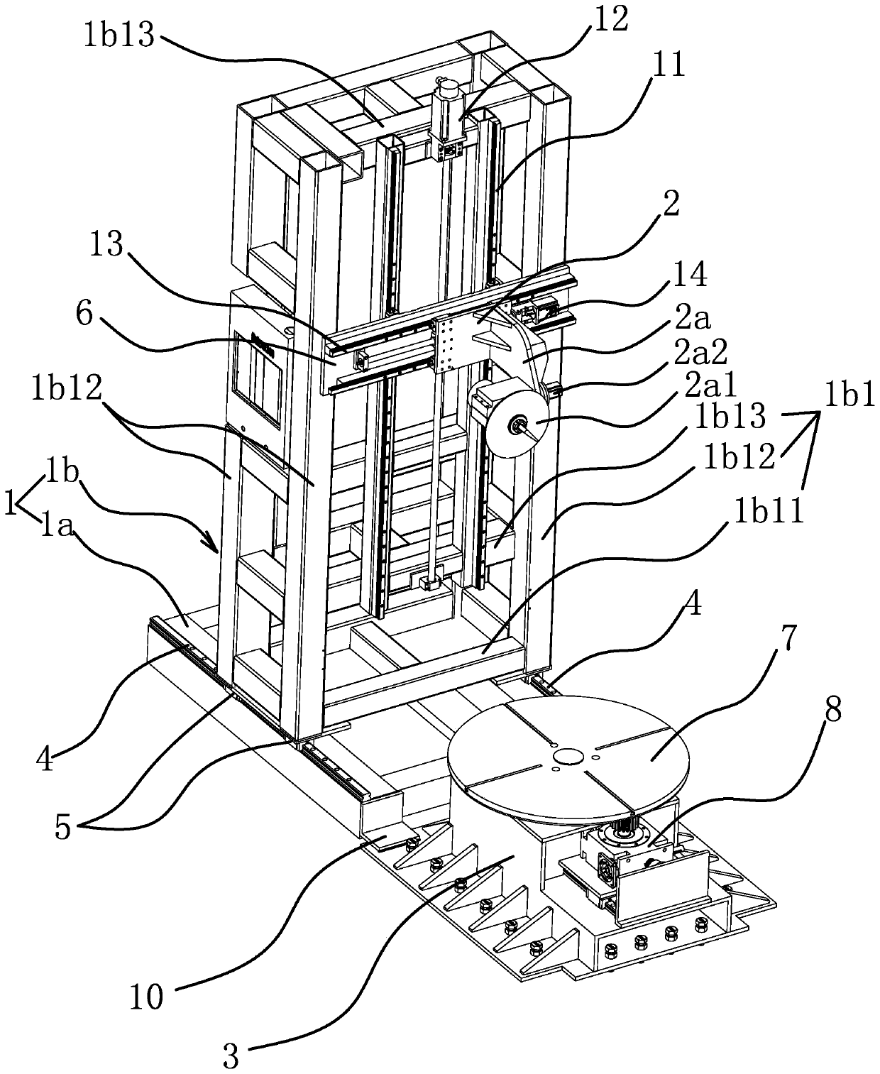
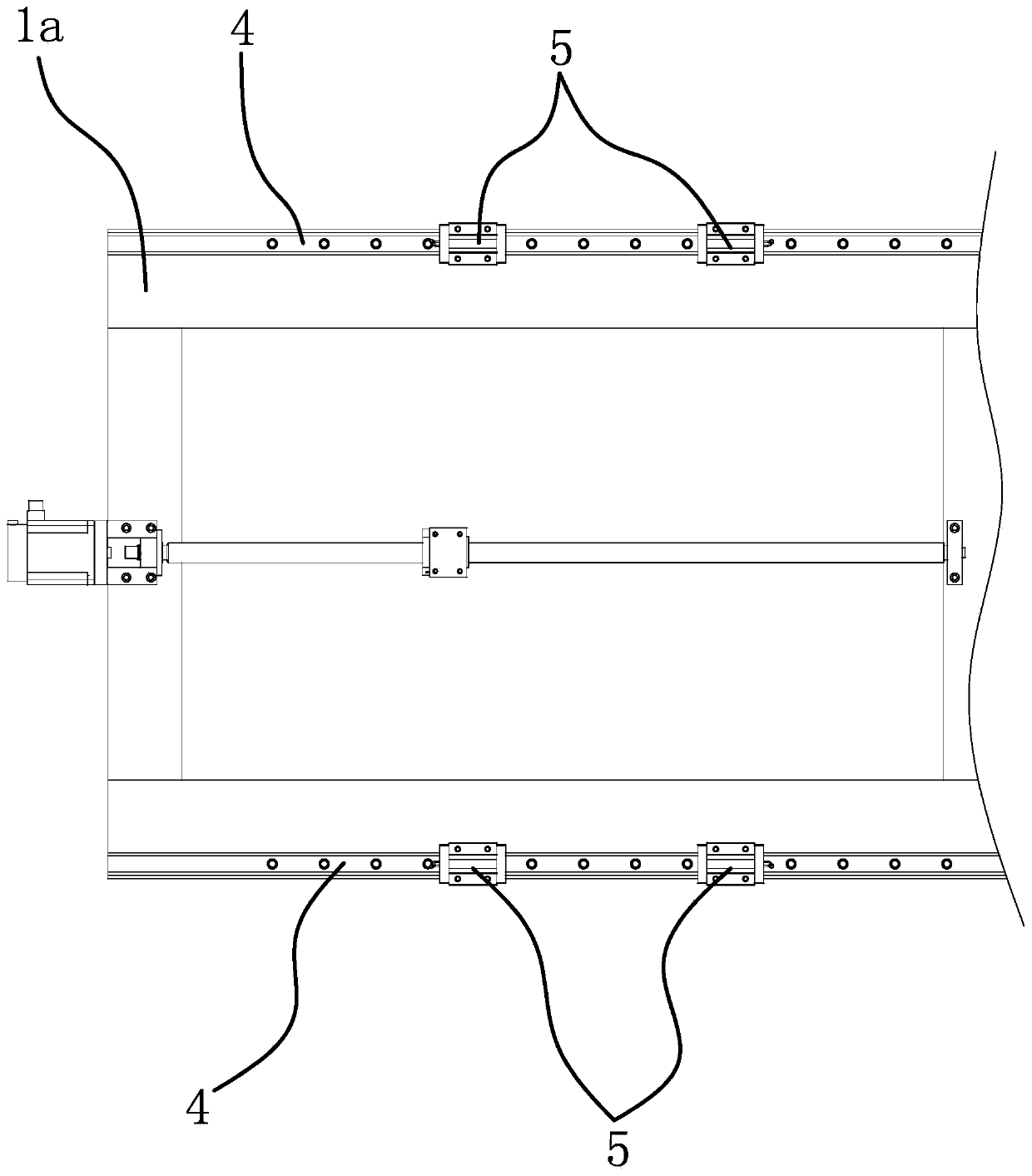
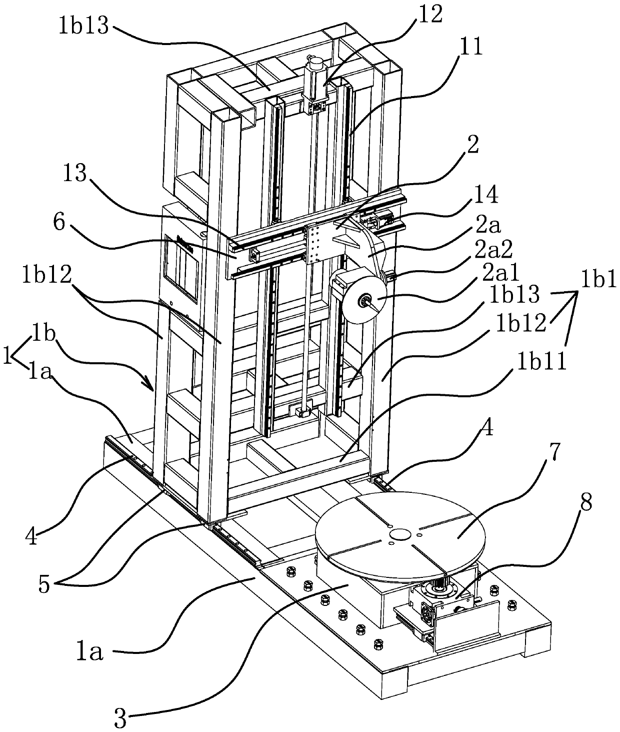
[0034] Specifically, as figure 1 As shown, in this embodiment, the engraving machine is a five-axis vertical engraving machine, including a frame 1, a tool holder 2 and a mounting seat 3 for clamping a vertical workpiece. The mounting seat 3 is provided with a workbench 7, The workbench 7 is a turntable structure, and the workbench 7 is driven by a rotating motor 8 . Wherein, the frame 1 comprises a base 1a and a three-dimensional mobile frame 1b arranged on the top of the base 1a, the base 1a is a flat frame structure, the three-dimensional mobile frame 1b is a columnar and vertically arranged frame structure as a whole, and the three-dimensional mobile frame 1b The length in the horizontal longitudinal direction is smaller than the length of the base 1a in the horizontal longitudinal direction. The mounting bases 3 are arranged side by side at one end of the base 1a and connected by a connecting piece 10, and are fixed relative to the base 1a. The connecting piece 10 can ad...

Embodiment 2

[0039] The technical solution in this embodiment is basically the same as the technical solution in Embodiment 1, the difference is that in this embodiment, such as image 3 As shown, the mounting base 3 is directly fixed on one end of the base 1a.

Embodiment 3

[0041] The technical solution in this embodiment is basically the same as the technical solution in Embodiment 1, the difference is that in this embodiment, such as Figure 4 As shown, the mounting seat 3 is arranged separately from the base 1a and is located at one end of the base 1a.


PUM


Abstract

The invention provides a vertical engraving machine, and belongs to the technical field of machining equipment. The problem about how to improve engraving precision is solved. The vertical engraving machine comprises a machine frame, a tool frame and a mounting base, wherein the machine frame comprises a base and a three-dimensional moving frame arranged above the base and used for mounting the tool frame; at least two sliding rails are fixedly arranged on the base in parallel; the three-dimensional moving frame is of a framework structure which is integrally columnar and vertically arranged,and the width direction of the three-dimensional moving frame is consistent with the direction of the sliding rails; two sliding blocks are respectively fixed on two sides of the bottom of the three-dimensional moving frame, and each sliding block is in sliding connection with the corresponding sliding rail; and the mounting base is immobile relative to the base and is arranged on one end of the sliding rails. Through the design, the three-dimensional moving frame moves horizontally and longitudinally with a tool, and the mounting base does not move during machining, so that the problem that the engraving precision is influenced caused by inaccurate clamping and positioning due to instable movement of the workpiece is avoided, and the engraving precision of the engraving machine is improved.

Description

technical field [0001] The invention belongs to the technical field of mechanical processing equipment, and relates to a vertical engraving machine. Background technique [0002] From the processing principle, engraving is a combination of drilling and milling. It has a wide range of applications, including woodworking engraving machines, laser engraving machines, advertising engraving machines, jade engraving machines, stone engraving machines, cylindrical engraving machines, etc. The engraving machine has a wide range of applications. Widely used, and even replaced the hand-carving technology, which laid the foundation for the mass and rapid production of products. The engraving machine is divided into vertical engraving machine and horizontal engraving machine, among which the vertical engraving machine is mainly for engraving the columnar workpiece set up vertically. [0003] For example, the Chinese patent [Application No.: 201520260602.0] discloses a large-scale verti...

Claims


Application Information

Patent Timeline
Patent Type & Authority Applications(China)
IPC IPC(8): B44B1/00B44B1/06
CPCB44B1/00B44B1/06
Inventor 吴善旺
Owner 吴善旺
Learn More