Carving machine

A technology of engraving machine and frame, applied in the field of engraving machines, can solve the problems of inability to achieve rough machining and finishing, difficult to ensure the machining accuracy of the engraving machine, and low engraving accuracy of the engraving machine, so as to reduce personal injury, improve the engraving accuracy, The effect of improving engraving efficiency

Active Publication Date: 2016-12-14
玉环圣弘法数控雕刻设备有限公司
View PDF6 Cites 3 Cited by
  • Summary
  • Abstract
  • Description
  • Claims
  • Application Information

AI Technical Summary

Problems solved by technology

This engraving machine has the following disadvantages: 1. The engraving machine is a single tool, which cannot realize rough machining and finishing, so the engraving efficiency is low; The cascading arrangement between two driving mechanisms, such arrangement mode stability is relatively poor, is difficult to guarantee the machining accuracy of engraving machine; The stability of the installation method is poor. Therefore, the engraving machine is also connected to the counterweight at both ends of the lifting frame, which improves the stability of the lifting frame to a certain extent. However, the counterweight is easy to shake, so it still cannot fundamentally Solve the shortcomings of insufficient lifting stability of the lifting frame, resulting in low engraving accuracy of the engraving machine
Moreover, after adding structures such as counterweights and ropes, the structure of the engraving machine is complicated and the manufacturing cost is high.

Method used


Image

  • Carving machine
  • Carving machine
  • Carving machine

Examples


Embodiment 1

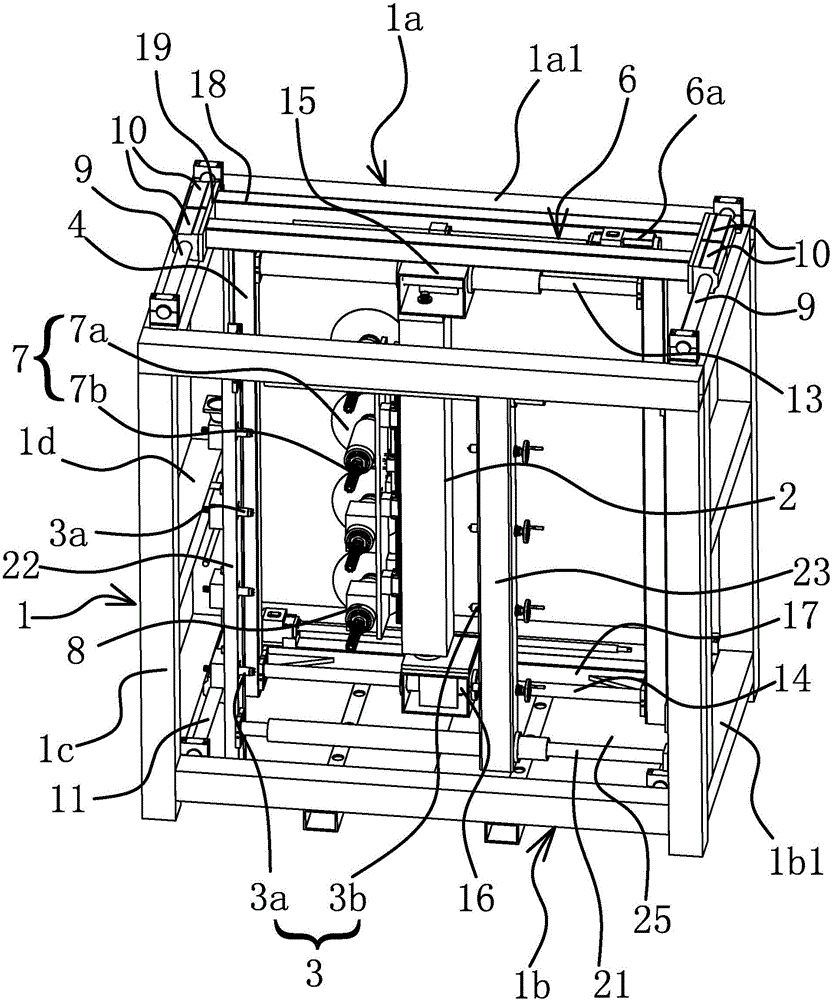
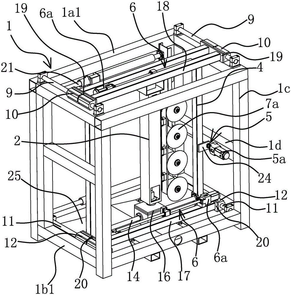
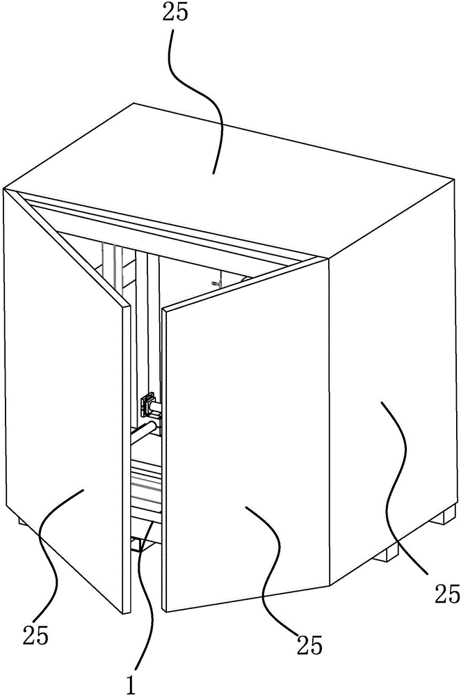
[0031] Such as figure 1 , 2 , 3, the engraving machine includes a frame 1, a workpiece clamping mechanism, a tool frame 2 and other structures, wherein the frame 1 includes an upper rectangular frame 1a formed by four upper beams 1a1, and a lower rectangular frame formed by four lower beams 1b1 1b and four connecting columns 1c between the upper rectangular frame 1a and the lower rectangular frame 1b, constitute a cube structure by the upper rectangular frame 1a, the lower rectangular frame 1b and four connecting columns 1c, on the top of the frame 1 of the cube structure Surface, four sides and bottom surface are provided with the dust-proof plate 25 that cube is closed, and wherein, the dust-proof plate 25 of frame 1 front side can be designed to be door-type structure, thereby facilitates the pick-and-place of workpiece. This engraving machine is mainly used for wood engraving, so it is easy to generate more dust during the engraving process. For this reason, when this en...


PUM


Abstract

The invention provides a carving machine, and belongs to the technical field of carving devices. The carving machine solves the technical problems that an existing carving machine is complex in structure and high in manufacturing cost. The carving machine comprises a machine frame and a workpiece clamping mechanism arranged in the machine frame. A straight-strip-shaped tool frame located on one side of the workpiece clamping mechanism is further arranged in the machine frame. Clamping assemblies arrayed in the vertical direction are arranged in the workpiece clamping mechanism. A rectangular vertically-arranged movement frame is arranged in the machine frame and is driven by a first lead screw mechanism to move back and forth in the horizontal and longitudinal directions. The tool frame mentioned above is arranged in the vertical direction, connected to the interior of the movement frame and driven by a second lead screw mechanism to move back and forth in the horizontal and transverse directions. Tool assemblies corresponding to the clamping assemblies one to one in number are arranged on the tool frame. Each tool assembly is driven by a corresponding carving motor. The carving machine has the beneficial effects of being high in carving precision and carving efficiency.

Description

technical field [0001] The invention belongs to the technical field of engraving equipment, and relates to an engraving machine. Background technique [0002] From the processing principle, engraving is a combination of drilling and milling. It has a wide range of applications, including woodworking engraving machines, laser engraving machines, advertising engraving machines, jade engraving machines, stone engraving machines, cylindrical engraving machines, etc. The engraving machine is a new type of CNC equipment in recent years. Its working principle is very similar to that of a CNC milling machine. The three axes of the control machine are automatically moved in a jog and continuous manner, so as to achieve the effect of automatic engraving. Its application range is very wide , and even replaced the hand-carving technology, which laid the foundation for mass and rapid production of products. [0003] For example, the Chinese patent literature has provided a vertical nume...

Claims


Application Information

Patent Timeline
Patent Type & Authority Applications(China)
IPC IPC(8): B44B1/00B44B1/06
CPCB44B1/003B44B1/06B44B2700/04B44B2700/12
Inventor 吴善旺
Owner 玉环圣弘法数控雕刻设备有限公司
Why Eureka
Try Eureka