A machine-made sand automatic loading system

A kind of machine-made sand and automatic technology, applied in the direction of conveyor, loading/unloading, conveyor objects, etc., to achieve the effect of reasonable structure design, reduce operation process and meet the use requirements

Active Publication Date: 2022-06-14
安徽达晶建筑材料有限公司
View PDF8 Cites 0 Cited by
  • Summary
  • Abstract
  • Description
  • Claims
  • Application Information

AI Technical Summary

Problems solved by technology

[0004] With the development of automation, all walks of life are moving towards automation. At present, the loading of sand trucks is mostly carried out by excavators. There is no need for manual loading, which saves manpower, but the frequent retrieving process of the excavator is cumbersome to operate, and the cost of retrieving and discharging materials is not low, and there will be a large amount of sand and gravel during loading and unloading, which will affect the site environment , and the blanking of buckets is used in loading, which is basically concentrated in the middle of the carriage. In order to reduce scattering at the edge, the edge blanking will not be carried out directly. It is difficult to achieve uniform laying of the materials in the carriage, thus affecting other The amount of the loading beam cannot achieve a more reasonable loading effect, and the loading method needs to be improved

Method used


Image

  • A machine-made sand automatic loading system
  • A machine-made sand automatic loading system
  • A machine-made sand automatic loading system

Examples


Embodiment Construction

[0029] Figure 5 It is a schematic diagram of the cross-sectional structure of the endless conveyor belt.

[0030] Figure 6 It is a structural schematic diagram of the adjustable distance between two material guide plates.

[0031] Reference signs:

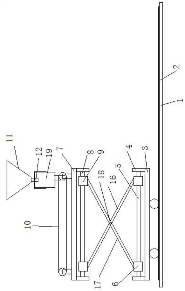
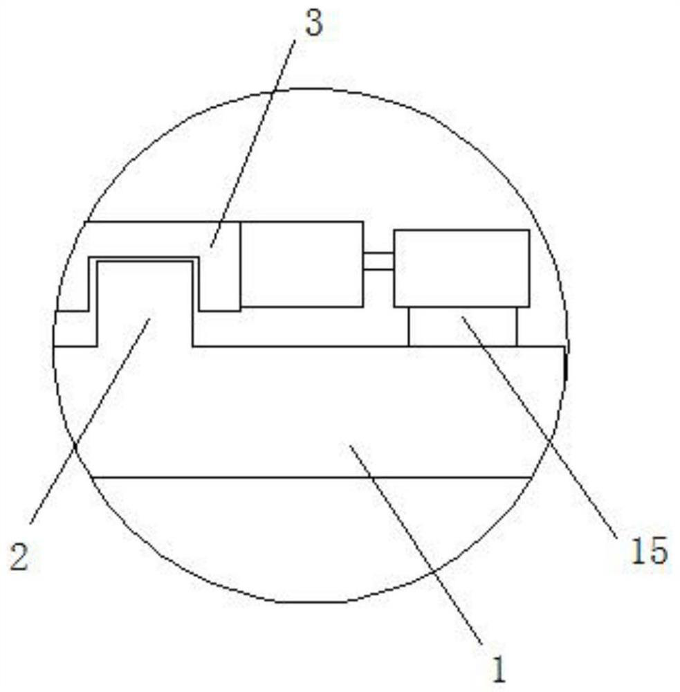
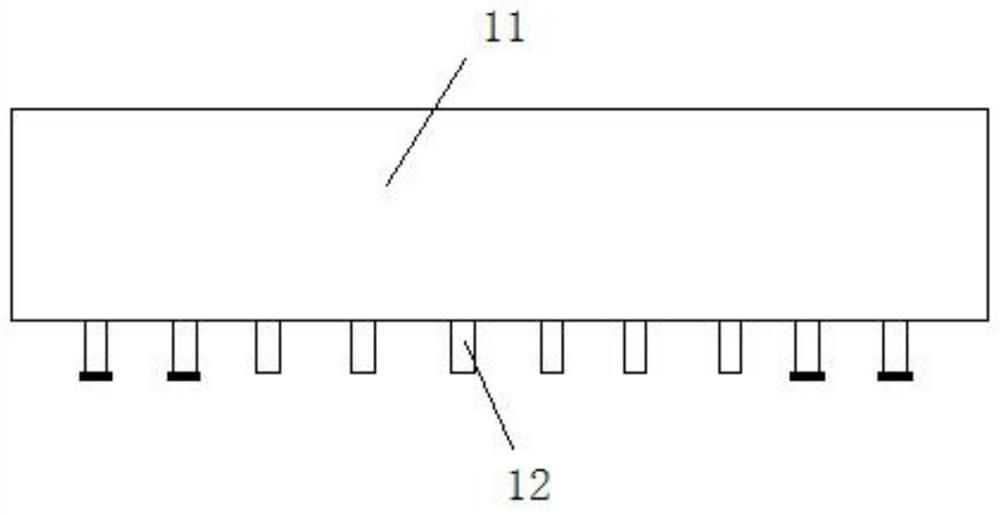
[0032] 1. Base; 2. Guide rail; 3. Moving seat; 4. Fixed support; 5. Screw rod one; 6. Slider one; 7. Fixed beam; 8. Screw rod two; 9. Slider two; 10. Circulating conveyor belt; 11. Uniform hopper; 12. Discharge pipe; 13. Feeding hoist; 14. Storage hopper; 15. Tooth plate; 16. Rod body one; 17. Rod body two; , conveyor belt one; 10-2, conveyor belt two; 10-3, positioning protrusion; 10-4, positioning groove; 10-5, retaining pin; 10-6, rib; 19, guide plate; 20 , Adjusting the screw rod; 21, the guide seat; 22, the circular lifting conveyor belt; 23, the lifting material plate; 24, the blocking plate.

Detailed ways:

[0034] See attached picture.

[0035] An automatic loading system for machine-made sand, including two bases...


PUM


Abstract

The invention discloses an automatic loading system for machine-made sand, which comprises two bases arranged side by side, a moving seat is guided and installed on the base, fixed supports are respectively installed at both ends of the mobile seat, and screw rods are installed between the fixed supports 1. Slider 1 with two intervals is installed on the screw rod 1, and the screw rod 2 corresponding to the screw rod 1 is installed under the fixed beam above the moving seat, and the slider 2 with two intervals is installed on the screw rod 2. Slider 2 and the corresponding slider 1 are connected and fixed by a lifting frame. A circular conveyor belt is set up on the support. The feeding end of the circular conveyor belt is set up with a leveling hopper, and one side of the leveling hopper is set up with an inclined feeding lift. machine, the bottom end of the feeding hoist is the feed end, and the feed end is located in the storage hopper. The invention has high automation intensity, reduces the operation process of picking and unloading materials by the bucket truck, realizes automatic material spreading, and has no material scattered, ensures the site environment, reduces waste of sand and gravel, and meets the use requirements.

Description

Technical field: [0002] The invention relates to machine-made sand production and processing equipment, and mainly relates to an automatic loading system for machine-made sand. Background technique: [0004] With the development of automation, all walks of life are moving towards automation. At present, most of the loading of sand trucks is carried out by bucket machines. Although it does not require manual loading, it saves manpower, but bucket loaders The frequent retrieving process is cumbersome to operate, and the cost of retrieving and discharging materials is not low, and there will be a large amount of sand and gravel bulk materials during loading and unloading, which will affect the site environment, and the loading is carried out by bucket by bucket. , basically concentrated in the middle of the carriage, in order to reduce scattering at the edge, the edge blanking will not be carried out directly, it is difficult to achieve uniform laying of the materials in the ca...

Claims


Application Information

Patent Timeline
Patent Type & Authority Patents(China)
IPC IPC(8): B65G67/08B65G67/10B65G69/04B65G47/18B65G21/12B65G15/22B65G23/04B65G15/42B65G23/22
CPCB65G67/08B65G67/10B65G69/0408B65G47/18B65G21/12B65G15/22B65G23/04B65G15/42B65G23/22B65G2201/045
Inventor 刘海龙
Owner 安徽达晶建筑材料有限公司
Why Eureka
Try Eureka