Auxiliary carrying device for power equipment

A technology for handling devices and electrical equipment, which is applied to lifting devices, transportation and packaging, trolley accessories, etc., can solve the problems of unfavorable installation of electrical equipment, high production cost of cranes, high space requirements, etc., to achieve convenience and improve convenience. High performance and safety

Inactive Publication Date: 2021-02-26
JINHUA POWER TRANSMISSION & DISTRIBUTION ENG +1
View PDF5 Cites 2 Cited by
  • Summary
  • Abstract
  • Description
  • Claims
  • Application Information

AI Technical Summary

Problems solved by technology

[0002] In the substation, due to the narrow space in the old substation, it is quite inconvenient to carry by manpower. We need an upstairs machinery that can not only lift heavy objects, but also carry heavy objects. On the one hand, it can facilitate the upstairs of heavy objects such as electrical equipment It can also facilitate the installation of heavy production equipment such as power equipment in narrow switch cabinets. The existing lifting and upstairs can be carried and upstairs by cranes and forklifts. Due to the structural limitations of cranes and forklifts, space requirements are required It is very high, and if the power equipment is unreliably fixed during the lifting process, it will easily cause the power equipment to fall off, which will affect the safety performance during transportation. The production cost of the crane is also high, and it is not conducive to the installation of power equipment in the narrow switch cabinet.

Method used


Image

  • Auxiliary carrying device for power equipment
  • Auxiliary carrying device for power equipment
  • Auxiliary carrying device for power equipment

Examples


Embodiment Construction

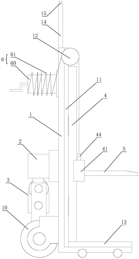
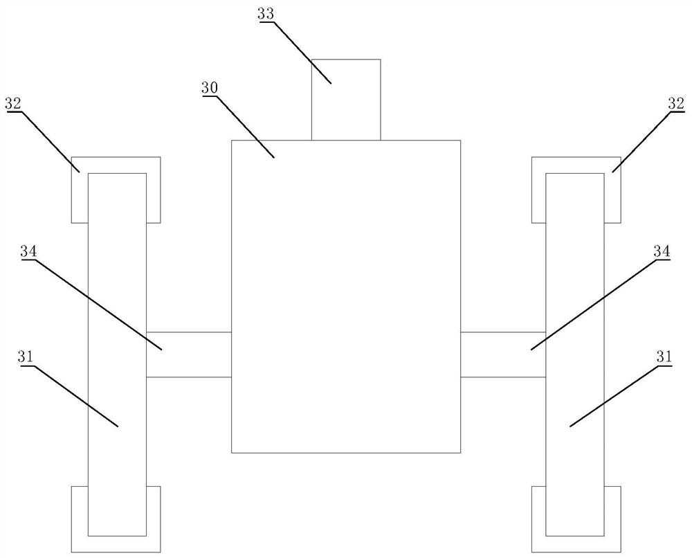
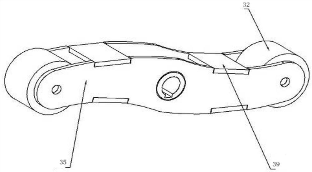
[0024] Such as figure 1 , figure 2 , image 3 , Figure 4 , Figure 5 As shown, an auxiliary transporting device for electric equipment includes a vehicle frame 1 and a driving motor 2 arranged on the back of the vehicle frame 1. The vehicle frame 1 is provided with traveling wheels 10, and the driving motor 2 is connected with a drive The frame 1 is a stair-climbing mechanism 3 for going up and down the stairs. The frame 1 is detachably mounted with a column 4. The column 4 is movably connected with a beam 41. The beam 41 is provided with a fork with adjustable width. Structure 5, the vehicle frame 1 is provided with a lifting mechanism 6 connected to the beam 41, the bottom end of the vehicle frame 1 is also provided with a load plate 13 detachably connected, and the fork structure 5 is also provided with a The connecting plate 57 connected to the load plate 13, when the load plate is installed on the vehicle frame, the load plate is used to fix heavy objects and facili...


PUM


Abstract

The invention relates to an auxiliary carrying device for power equipment. The auxiliary carrying device comprises a trolley frame and a driving motor, the driving motor is in transmission connectionwith a stair climbing mechanism, the trolley frame is further detachably provided with a stand column, the stand column is movably connected with a cross beam, the cross beam is provided with a fork tooth structure, the trolley frame is provided with a lifting mechanism, and the bottom end of the trolley frame is further detachably connected with a loading plate. The auxiliary carrying device hasthe advantages that the trolley frame can walk on the flat ground through walking wheels on the trolley frame, when a heavy object needs to be lifted, only the stand column needs to be installed on the trolley frame, lifting of the cross beam is adjusted through the lifting mechanism to achieve lifting of the heavy object, and when the heavy object needs to go upstairs, the stair climbing mechanism is driven by the driving motor to go upstairs and downstairs of the trolley frame. Therefore, according to the embodiment, the heavy object can be lifted and go upstairs at the same time on one trolley frame, the trolley frame is simple in structure, it is convenient to mount and dismount the trolley frame, the safety performance is high when the heavy object goes upstairs and is lifted, the overall use cost is low, and the trolley frame is not limited by space when used.

Description

technical field [0001] The invention relates to an auxiliary conveying device for electric equipment. Background technique [0002] In the substation, due to the narrow space in the old substation, it is quite inconvenient to carry by manpower. We need an upstairs machinery that can not only lift heavy objects, but also transport heavy objects. On the one hand, it can facilitate the upstairs of heavy objects such as electrical equipment. It can also facilitate the installation of heavy production equipment such as power equipment in narrow switch cabinets. The existing lifting and upstairs can be carried and upstairs by cranes and forklifts. Due to the structural limitations of cranes and forklifts, space requirements are required It is very high, and if the power equipment is unreliably fixed during the lifting process, it will easily cause the power equipment to fall off, thereby affecting the safety performance during transportation. The production cost of the crane is al...

Claims


Application Information

Patent Timeline
Patent Type & Authority Applications(China)
IPC IPC(8): B66F9/06B66F9/075B66F9/12B66F9/20B66F9/24
CPCB62B5/026B66F9/06B66F9/075B66F9/07504B66F9/12B66F9/142B66F9/20B66F9/24
Inventor 梁栋程军李策策毛水强徐勇军高寅黄刚王珏金涛吕红峰俞建新滕华繁王能朱建增杨振涛徐文韬
Owner JINHUA POWER TRANSMISSION & DISTRIBUTION ENG
Why Eureka
Try Eureka