
Rainwater biological filtration equipment

A biological filtration and equipment technology, which is applied in the fields of filtration treatment, runoff/rainwater treatment, biological water/sewage treatment, etc. It can solve the problems of decreased fluidity inside the biological filtration equipment and easy clogging of sand particles in the pores of the filter element, so as to avoid Effects of clogging, improving fluidity, and improving purification effect

Inactive Publication Date: 2021-02-26
赵杰
View PDF0 Cites 2 Cited by
  • Summary
  • Abstract
  • Description
  • Claims
  • Application Information

AI Technical Summary

Problems solved by technology

[0002] The use of rainwater is divided into indirect and direct. The direct use is to collect and store rainwater, and then purify the rainwater through biological filtration equipment, and then directly use it for washing roads, greening, car washing, flushing toilets, etc. The internal setting of biological filtration equipment There are vegetation and filter elements, and the sand particles can be intercepted through the filter elements, but because the filter elements inside the biological filtration equipment are in a static state, when the sand content in the rainwater is high, the sand particles are easy to block the pores of the filter elements, resulting in the rainwater in the biological filtration. The fluidity inside the equipment decreases, and it is difficult for rainwater to pass through the filter element, causing the sand particles in the rainwater to be easily suspended inside the biological filtration equipment, causing the sand particles in the rainwater to be directly discharged from the water purification outlet along with the rainwater

Method used


Image

  • Rainwater biological filtration equipment
  • Rainwater biological filtration equipment
  • Rainwater biological filtration equipment

Examples


Embodiment 1

[0024] as attached figure 1 to attach Image 6 Shown:

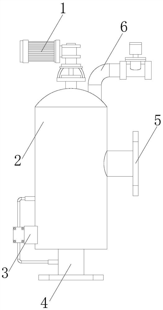
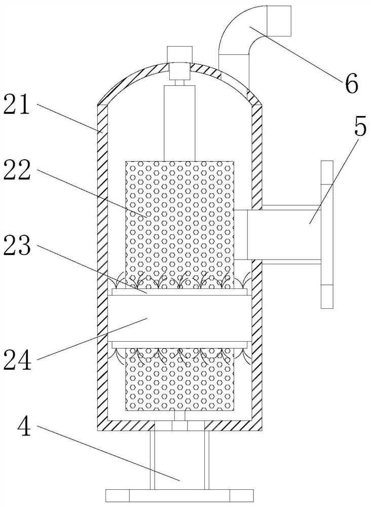
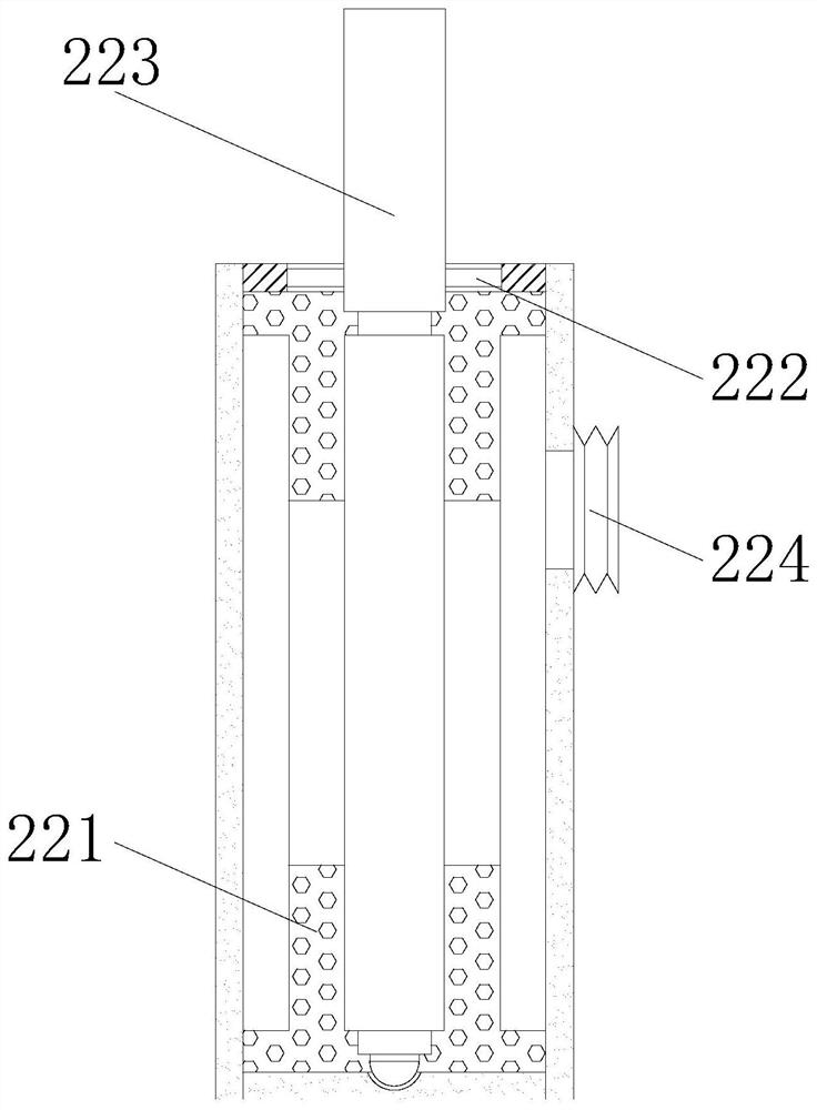
[0025] The present invention is a kind of rainwater biological filtration equipment, its structure comprises motor 1, filter tank 2, differential pressure controller 3, water inlet pipe 4, clean water discharge pipe 5, sewage discharge pipe 6, and described motor 1 is fixedly installed on the top of filter tank 2 The lower end of the filter tank 2 is provided with a differential pressure controller 3, the water inlet pipe 4 is fixedly installed on the bottom of the filter tank 2 and communicates with each other, and the clean water drain pipe 5 is embedded in the middle of the right end of the filter tank 2 and connected to each other. Through, the sewage pipe 6 is arranged on the top of the filter tank 2, and the filter tank 2 includes a tank body 21, a filter element device 22, a vegetation layer 23, and a shaking mechanism 24, and the lower end of the tank body 21 is embedded with a water inlet pipe 4 and Interconnec...

Embodiment 2

[0033] as attached Figure 7 to attach Figure 8 Shown:

[0034] Wherein, the shaking mechanism 24 includes a fixed tube 241, a push ball 242, an elastic rod 243, and a positioning mechanism 244. The outer surface of the fixed tube 241 is fixed to the inner wall of the tank body 21, and the push ball 242 is mounted on the filter element device with clearance fit. 22 inside the outer side of the lower end, the outer end of the push ball 242 is fixed to one end of the elastic rod 243, and the other end of the elastic rod 243 is welded to the inner wall of the fixed tube 241, the positioning mechanism 244 is located below the fixed tube 241, and the upper end of the positioning mechanism 244 Fixed with the middle part of the lower end of the filter element device 22, the push balls 242 and the elastic rods 243 are provided with six, and three as a group, which are respectively arranged at the left and right ends of the outer side of the filter element 221, which is beneficial to...


PUM


Abstract

The invention discloses rainwater biological filtration equipment which structurally comprises a motor, a filter tank, a differential pressure controller, a water inlet pipe, a purified water discharge pipe and a blow-off pipe. The motor is fixedly installed at the top of the filter tank, and the differential pressure controller is arranged at the lower end of the filter tank. Rainwater enters thetank body and is in contact with a vegetation layer for purification, sand grains in the rainwater are blocked through a filter element, and purified water flows from a telescopic hose and is finallydischarged from the interior of the purified water discharge pipe. The motor drives a rotating shaft to rotate, a cleaning plate scrapes the inner wall of the filter element, sand grains blocked in pores of the filter element are extruded out through scraping strips, and the situation that rainwater difficultly penetrates through the filter element is avoided. When rainwater is discharged in fromthe water inlet pipe, an elastic rod is impacted, so that a pushing ball is driven to abut against and extrude the two ends of the outer side of the filter element, the fluidity of the rainwater in the filter element is improved, meanwhile, part of sand particles adsorbed in pores of the filter element are shaken off, and the interior of the pores of the filter element is prevented from being blocked.

Description

technical field [0001] The invention relates to the field of biological filtering equipment, and more specifically, relates to a rainwater biological filtering equipment. Background technique [0002] The use of rainwater is divided into indirect and direct. The direct use is to collect and store rainwater, and then purify the rainwater through biological filtration equipment, and then directly use it for washing roads, greening, car washing, flushing toilets, etc. The internal setting of biological filtration equipment There are vegetation and filter elements, and the sand particles can be intercepted through the filter elements, but because the filter elements inside the biological filtration equipment are in a static state, when the sand content in the rainwater is high, the sand particles are easy to block the pores of the filter elements, resulting in the rainwater in the biological filtration. The fluidity inside the equipment decreases, and it is difficult for rainwat...

Claims


Application Information

Patent Timeline
IPC IPC(8): C02F3/32C02F1/00
CPCC02F1/001C02F3/32C02F2103/001
Inventor 赵杰
Owner 赵杰
Learn More