Bulldozer

A bulldozer and bulldozer shovel technology, applied in the direction of earth mover/shovel, mechanically driven excavator/dredger, construction, etc. Good performance, improve transmission fluency, and improve the effect of flexibility

Inactive Publication Date: 2021-02-26
黄华贵
View PDF0 Cites 0 Cited by
  • Summary
  • Abstract
  • Description
  • Claims
  • Application Information

AI Technical Summary

Problems solved by technology

[0003] When the bulldozer in the prior art is actually working, the amount of soil shoveled is different each time, and the load-bearing force of the bulldozer is different. The force on the connecting device is sometimes large and sometimes small, which will reduce the smoothness of transmission. When shoveling, the shovel head hits the material It also produces a certain impact force on the connecting device and causes damage.

Method used


Image

  • Bulldozer
  • Bulldozer
  • Bulldozer

Examples


Embodiment 1

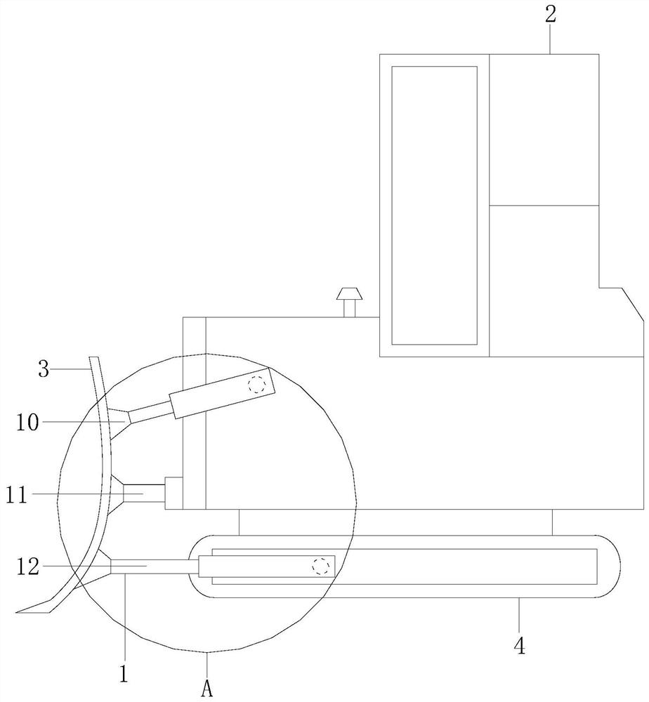
[0025] Example 1 see figure 1 , 2 , the present invention provides a bulldozer technical solution: its structure includes a connection device 1, a fuselage 2, a bulldozer blade 3, and a road wheel 4, and the bulldozer blade 3 is connected to the body 2 and the road wheel 4 through the connection device 1 , the traveling wheel 4 is installed on the fuselage 2, the connecting device 1 is composed of a cylinder 10, a fulcrum structure 11, and a buffer structure 12, and the cylinder 10 cooperates with the buffer structure 12 to form a driving force and a pushing buffer force , the cylinder 10 is installed on the fuselage 2, the fulcrum structure 11 is locked on the fuselage 2, the fulcrum structure 11 realizes slight turning of the bulldozing blade 3, and the slow support structure 12 is installed on the road wheel 4 on.

[0026] The equipment drives the bulldozing blade 3 to bulldoze and shovel soil through the connection device 1, the cylinder 10 cooperates with the buffer su...

Embodiment 2

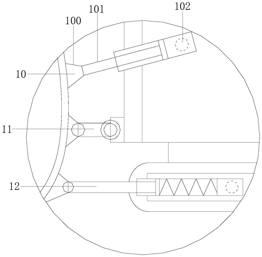
[0027] Example 2 see Figure 3-6 , the present invention provides a bulldozer technical solution: the structure of the cylinder 10 includes a cylinder body cover 100, a cylinder body 101, a cylinder body shaft 102, the cylinder body cover 100 is installed on the cylinder body 101, and the cylinder The main body 101 is equipped with a cylinder housing shaft 102, and the shaft structure 11 includes a shaft housing cover 110, a shaft support rod 111, and a support lock frame 112. Frame 112 is installed and connected, and the support shaft support bar 111 includes double rotating shaft 1110, transmission pulley 1111, main rod body 1112, motor 1113, and described driving pulley 1111 is installed on the double rotating shaft 1110, and described main rod body 1112 is connected with double rotating shaft 1110, The motor 1113 is installed and connected, and the double rotating shaft 1110 is installed and connected to the motor 1113 and both are electrically connected. The double rotati...


PUM


Abstract

The invention discloses a bulldozer. The bulldozer structurally comprises a connecting device, a bulldozer body, a dozer blade and walking wheels, the dozer blade is connected with the bulldozer bodyand the walking wheels through the connecting device, the walking wheels are installed on the bulldozer body, the connecting device is composed of an air cylinder, a supporting shaft structure and a slow supporting structure, the air cylinder is installed on the bulldozer body, the supporting shaft structure is locked on the bulldozer body, and the slow supporting structure is installed on the walking wheels; and the air cylinder comprises a cylinder body installation cover, an air cylinder body and a cylinder body installation shaft, the cylinder body installation cover is installed on the air cylinder body, the air cylinder body is provided with the cylinder body installation shaft, the supporting shaft structure comprises a supporting shaft installation cover, a supporting shaft supporting rod and a supporting lock frame, and the supporting shaft supporting rod is connected with the supporting shaft installation cover and the supporting lock frame. According to the bulldozer, the air cylinder and the slow supporting structure are matched to form pushing force and pushing buffering force, the bearing stress of the dozer blade is reasonably distributed, the transmission stabilityis improved, the impact force during operation is greatly reduced, and the supporting shaft structure assists in turning over the dozer blade to further improve the transmission smoothness.

Description

technical field [0001] The invention relates to the field of agricultural equipment, in particular to a bulldozer. Background technique [0002] A bulldozer is a kind of engineering vehicle with a large metal bulldozer blade installed in front. When in use, the bulldozer blade is put down to cut and push mud, sand and stones forward. or flat. [0003] When the bulldozer in the prior art is actually working, the amount of soil shoveled is different each time, and the load-bearing force of the bulldozer is different. The force on the connecting device is sometimes large and sometimes small, which will reduce the smoothness of transmission. When shoveling, the shovel head hits the material It also produces a certain impact force on the connecting device and causes damage. Contents of the invention [0004] The main purpose of the present invention is to overcome the deficiencies of the prior art and provide a bulldozer to solve the problem that when the bulldozer is actuall...

Claims


Application Information

Patent Timeline
Patent Type & Authority Applications(China)
IPC IPC(8): E02F3/76E02F3/84
CPCE02F3/76E02F3/7618E02F3/84
Inventor 黄华贵
Owner 黄华贵
Why Eureka
Try Eureka