A fast binding device for steel bars for construction

A technology for construction and steel bars, which is applied in the direction of construction, building structure, and building materials processing, etc. It can solve the problems of low binding efficiency of steel bars and main steel bars, unfavorable construction efficiency, and laborious withdrawal, so as to improve practicality and safety. Flexibility, improve binding efficiency, and ensure the effect of construction quality

Active Publication Date: 2022-01-28
QINGDAO HAIDE ROAD & BRIDGE ENG
View PDF17 Cites 0 Cited by
  • Summary
  • Abstract
  • Description
  • Claims
  • Application Information

AI Technical Summary

Problems solved by technology

[0007] 1. After the steel bars are placed on the fixture, during the actual binding, there is a situation that the installation height of the steel bars needs to be temporarily adjusted according to the actual situation of the construction site or when there are construction errors. However, the fixture structure in the above scheme is put into the locking clamp block. The rubber latches on the surface are locked, so it cannot be adjusted after being clamped. When there is a construction error, it cannot be compensated, and the practicability needs to be improved.
[0008] 2. Several steel bars on the same side can only be adjusted at the same time, and the spacing is set to be the same. Individual steel bars cannot be adjusted accurately. However, during construction, there are various situations, so precise adjustments cannot be made according to actual construction requirements.
[0009] 3. The two side support plates and the two supporting plates need to be manually adjusted to complete the binding work of the steel bars, which is time-consuming and laborious, resulting in low binding efficiency of the steel bars and the main steel bars
[0010] 4. The overall fixture is too large, and there is no sliding structure designed. After the steel bars are bundled, it is laborious to withdraw, which is not conducive to improving construction efficiency.

Method used


Image

  • A fast binding device for steel bars for construction
  • A fast binding device for steel bars for construction
  • A fast binding device for steel bars for construction

Examples


Embodiment Construction

[0053] The technical solutions of the present invention will be further described below in conjunction with the accompanying drawings and through specific implementation methods.

[0054] Wherein, the accompanying drawings are only for illustrative purposes, showing only schematic diagrams, rather than physical drawings, and should not be construed as limitations on this patent; in order to better illustrate the embodiments of the present invention, some parts of the accompanying drawings will be omitted, Enlarged or reduced, does not represent actual product size.

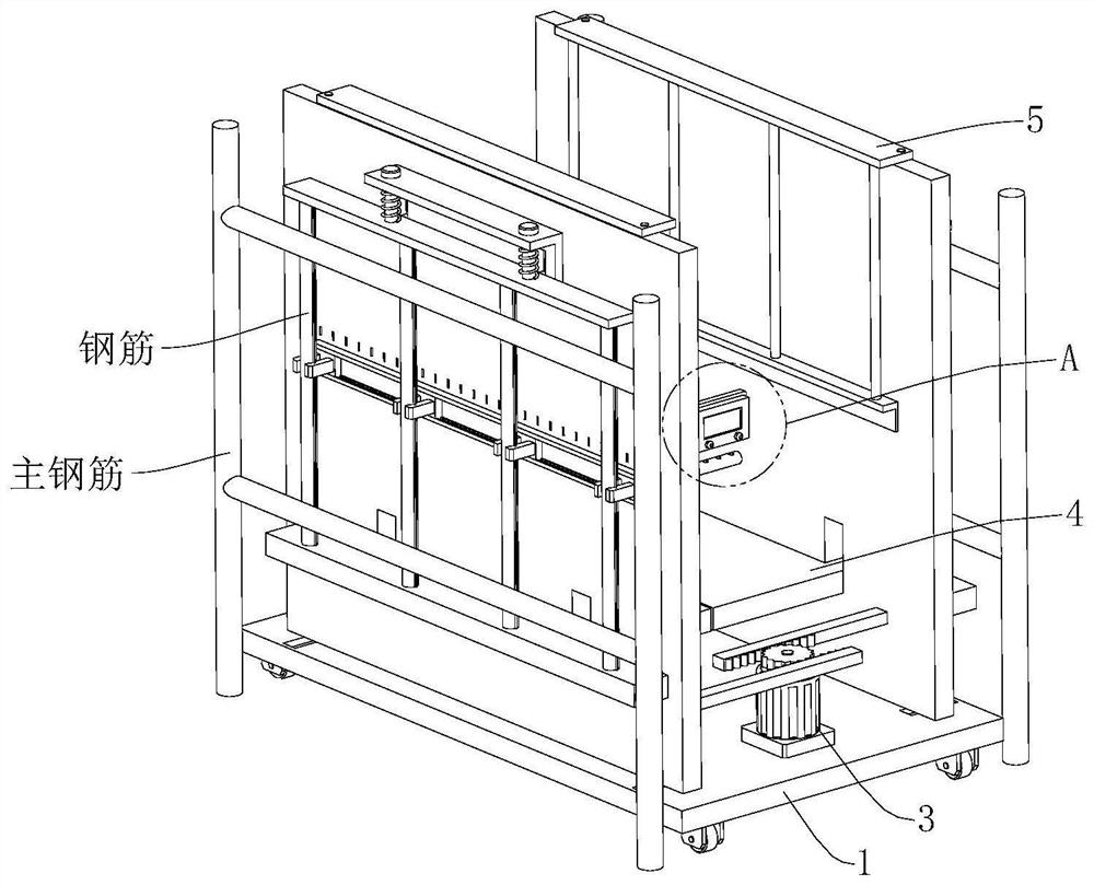
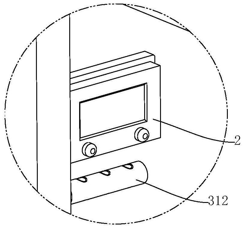
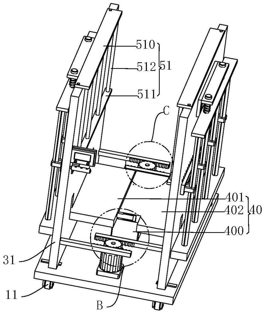
[0055] refer to Figure 1 to Figure 9 The shown fast binding device for steel bars for construction includes a bottom plate 1, and also includes a controller 2, an outward expansion mechanism 3, a longitudinal adjustment mechanism 4 and a horizontal adjustment mechanism 5, and the outer expansion mechanism 3 is arranged on the top of the bottom plate 1 For binding steel bars, the outward expansion mechanism 3 inc...


PUM


Abstract

The invention relates to the technical field of building construction, in particular to a fast binding device for steel bars for construction, which includes a bottom plate, a controller, an external expansion mechanism, a longitudinal adjustment mechanism and a horizontal adjustment mechanism. The external expansion mechanism includes a drive assembly and two vertical adjustment mechanisms. plate, the longitudinal adjustment mechanism is set on the top of the bottom plate to adjust the installation height of the reinforcement, the longitudinal adjustment mechanism includes a jacking assembly and two limit assemblies, and the horizontal adjustment mechanism is set on the outer wall of the vertical plate for To adjust the installation spacing of steel bars, the horizontal adjustment mechanism includes two slide rails, two locking assemblies and several clamping assemblies, and the driving assembly and jacking assembly are electrically connected to the controller. The device and method for quickly binding steel bars can effectively avoid construction errors, quickly adjust the installation height, and accurately adjust the horizontal spacing of steel bars after clamping. At the same time, manual adjustment is not required, saving time and effort, and it is convenient to withdraw after binding .

Description

technical field [0001] The invention relates to the technical field of building construction, in particular to a fast binding device for steel bars for building. Background technique [0002] The shear walls and supporting columns in modern building construction are often constructed by cast-in-place concrete. Before the construction of cast-in-place concrete, the reinforcement frame needs to be set. The reinforcement frame needs to be buried with the main steel bars first. After the main steel bars are buried The inner ends of the main steel bars are bundled with longitudinal steel bars to increase the stability of the concrete columns. [0003] When bundling the longitudinal steel bars, it needs to be adjusted to a suitable distance. The steel bar positioning fixture is usually used for binding the steel bars. The existing steel bar positioning fixture is to position and place the steel bars by slotting on the channel steel. This kind of fixture needs to be locked in the p...

Claims


Application Information

Patent Timeline
Patent Type & Authority Patents(China)
IPC IPC(8): E04G21/12
CPCE04G21/123
Inventor 赵桂荣陈婷婷
Owner QINGDAO HAIDE ROAD & BRIDGE ENG
Why Eureka
Try Eureka