A three-point adjustment method for regulating valve with electric valve positioner

A valve positioner, regulating valve technology, applied in valve details, valve operation/release device, valve device and other directions, can solve the problems of long time-consuming adjustment, difficult to find the zero point, large error in the starting point confirmation process, etc. The effect of high efficiency, high accuracy and simple adjustment process

Active Publication Date: 2022-07-05
SHAANXI YANCHANG PETROLEUM GRP
View PDF0 Cites 0 Cited by
  • Summary
  • Abstract
  • Description
  • Claims
  • Application Information

AI Technical Summary

Problems solved by technology

[0004] The purpose of the three-point adjustment method of a regulating valve with an electric valve positioner provided by the present invention is to overcome the cumbersome adjustment process of the five-point method in the prior art, the adjustment takes a long time, and the starting point (ie zero point) confirmation process error Large, the zero point of the largest defect is difficult to find, and the operator cannot understand the essence and principle of the adjustment

Method used


Image

  • A three-point adjustment method for regulating valve with electric valve positioner

Examples


Embodiment 1

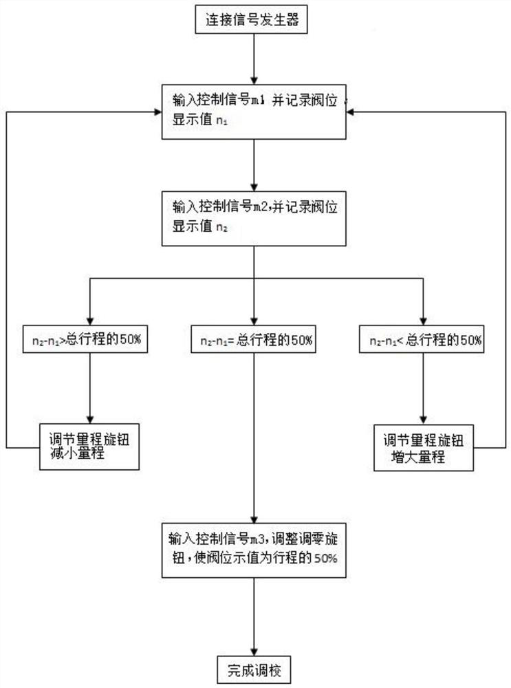
[0022] like figure 1 As shown in the figure, a three-point adjustment method of a regulating valve with an electric valve positioner includes the following steps:

[0023] 1) Connect the calibrated regulating valve to the signal generator;

[0024] 2) In the regulating valve being calibrated, input the control signal m 1 , record the control signal m 1 Corresponding valve position display value n 1 ;

[0025] 3) In the calibrated control valve, input the control signal m 2 , record the control signal m 2 Corresponding valve position display value n 2 ;

[0026] 4) Calculate n 2 and n 1 Compare the difference with 50% of the total stroke of the regulating valve being calibrated; adjust the range knob according to the comparison result until the difference is equal to 50% of the total stroke of the regulating valve being calibrated;

[0027] 5) Input control signal m 3 , adjust the valve position display value to the position of 50% of the total stroke of the adjustin...

Embodiment 2

[0030] On the basis of Embodiment 1, further, the control signal m 1 The range is: 4mA≤m 1 ≤12mA. Limit control signal m 1 range, the purpose is for the next calibration point, that is, the control signal m 2 The value of , the range design is reasonable.

[0031] Further, the control signal m 2 is m 1 +8. why m 2 value m 1 +8 is because the general output signal range is 4mA-20mA, that is, the total output signal range is (20-4)mA, that is, 16mA. The purpose is to achieve m 2 -m 1 / 16 is 50% of the total range of the output signal, and finally realizes a one-to-one correspondence between the interval value of the two output signals and the difference between the two indications corresponding to the travel indicator of the regulating valve actuator and the total travel of the actuator.

[0032] Further, described step 2) input control signal m 1 , when the valve position displays the value n 1 When it is greater than 50% of the total stroke of the regulating valve ...


PUM


Abstract

The invention belongs to the technical field of chemical energy instruments, and specifically provides a three-point adjustment method for a regulating valve with an electric valve positioner, which connects the regulating valve to be calibrated with a signal generator; in the regulating valve to be calibrated, an input signal m 1 , record the corresponding valve position display value n 1 ;input signal m 2 , record m 2 Corresponding valve position display value n 2 ; compute n 2 and n 1 the difference, compare the difference with 50% of the total stroke; adjust the range knob according to the comparison result until the difference is equal to 50% of the total stroke; input signal m 3 , adjust the valve position display value to 50% of the total stroke position through the zero adjustment knob, and the adjustment is completed; it solves the cumbersome adjustment process of the five-point method, the adjustment time is long, the error in the starting point confirmation process is large, and the maximum defect zero point is difficult If it is accurate, the operator cannot understand the essence and principle of the adjustment. The invention realizes three-point adjustment, the adjustment process is simple, the principle is clear at a glance, the efficiency is high, the accuracy rate is high, and there is no error, and the operator can easily grasp and understand the adjustment. School principles.

Description

technical field [0001] The invention belongs to the technical field of chemical energy instruments, in particular to a three-point adjustment method of a regulating valve with an electric valve positioner. Background technique [0002] At this stage, the adjustment method of regulating valve with electric valve positioner commonly used in the chemical energy instrument industry can be called "five-point method". That is, input 4mA, 8mA, 12mA, 16mA, 20mA five control signals, each input control signal is compared with the theoretical corresponding value of the actuator stroke card: 0, 25%, 50%, 75%, 100%, and then observe each Each input signal corresponds to the indication value of the actuator travel plate, so as to judge the size of the range. Repeat this process to adjust the range knob until the range is calibrated, and each adjustment requires a zero-adjustment operation. Finally, input a 4mA control signal, and adjust the zero-adjustment knob so that the pointer of th...

Claims


Application Information

Patent Timeline
Patent Type & Authority Patents(China)
IPC IPC(8): F16K31/02F16K37/00
CPCF16K31/02F16K37/0041
Inventor 李瑞吴红梅井争平
Owner SHAANXI YANCHANG PETROLEUM GRP
Why Eureka
Try Eureka