Air conditioning equipment, control method, control device and readable storage medium

A technology of air-conditioning equipment and control methods, which is applied to mechanical equipment, refrigeration and liquefaction, lighting and heating equipment, etc. It can solve the problems of long time for the air outlet temperature of the indoor unit, long system piping, and long refrigerant migration time, etc., to achieve Guarantee the heating experience, prevent the temperature from dropping, and improve the effect of heat dissipation

Pending Publication Date: 2021-02-26
HEFEI MIDEA HEATING & VENTILATING EQUIP +1
View PDF7 Cites 0 Cited by
  • Summary
  • Abstract
  • Description
  • Claims
  • Application Information

AI Technical Summary

Problems solved by technology

During the whole process, the refrigerant of the system needs to be migrated twice, especially for multi-split units, the piping of the system is long, and the refrigerant migration time will be longer, so it will take a long time for the indoor unit to reach the higher air outlet temperature after defrosting. long

Method used


Image

  • Air conditioning equipment, control method, control device and readable storage medium
  • Air conditioning equipment, control method, control device and readable storage medium
  • Air conditioning equipment, control method, control device and readable storage medium

Examples


Embodiment 1

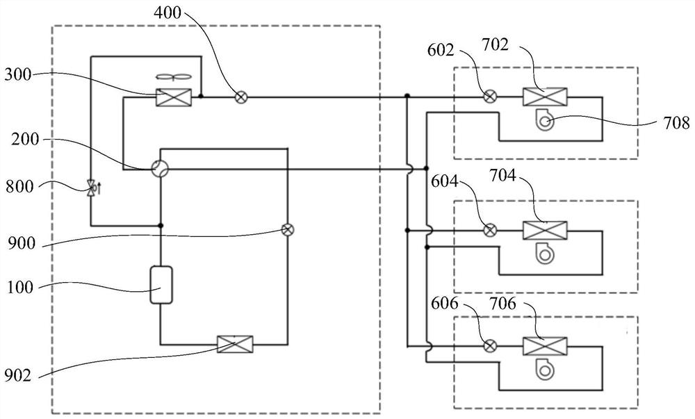
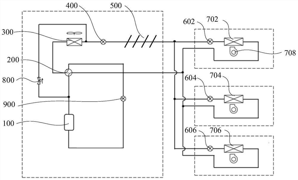
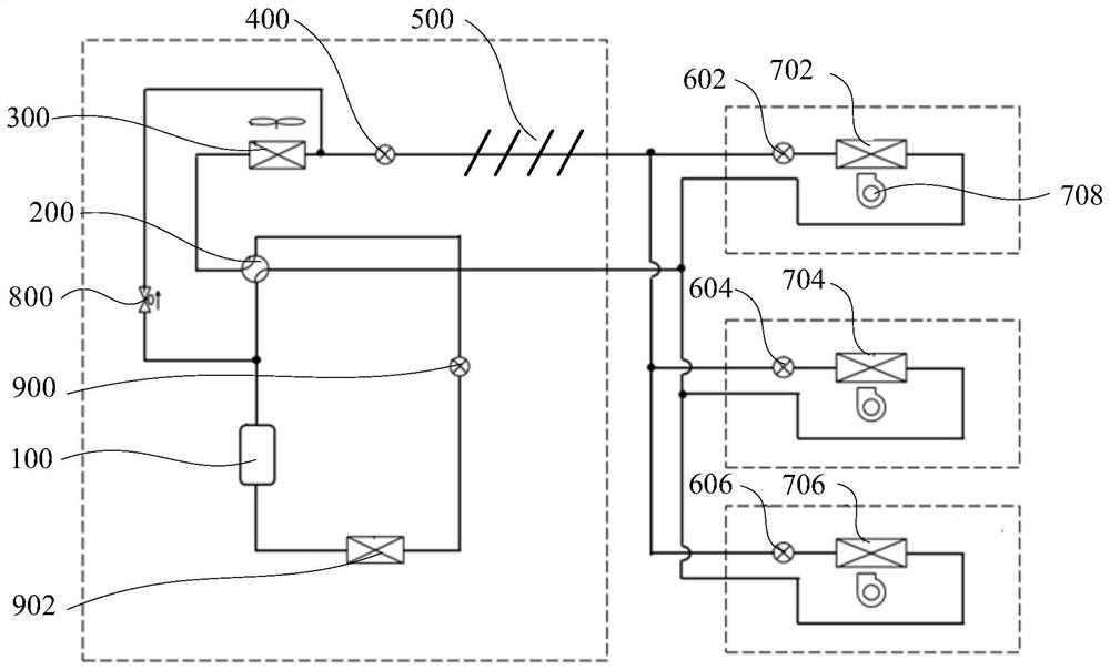
[0061] figure 1 It shows one of the structural schematic diagrams of the air conditioner according to the embodiment of the present invention, figure 2 Shows the second structural schematic diagram of the air conditioner according to the embodiment of the present invention, image 3 It shows the third structural schematic diagram of the air conditioner according to the embodiment of the present invention.

[0062] In some embodiments of the present invention, such as figure 1 , figure 2 and image 3 As shown, an air conditioner is provided, including: a compressor 100, an outdoor heat exchanger 300, a bypass pipeline, a blocking device 800, a first throttle 900, an electric heating device 902 and a controller. Wherein, the compressor 100 includes an exhaust port. The first end of the bypass line is connected to the exhaust port, and the second end of the bypass line is connected to the inlet of the outdoor heat exchanger 300 , that is, the exhaust bypass. The blocking ...

Embodiment 2

[0074] In some embodiments of the present invention, such as figure 1 , figure 2 and image 3 As shown, compressor 100 also includes an air intake. The air conditioner also includes at least one indoor heat exchanger and a four-way valve 200 . Wherein, at least one indoor heat exchanger is connected with the outdoor heat exchanger 300 .

[0075] Specifically, three indoor heat exchangers are used as an example for illustration. Thus, at least one indoor heat exchanger includes a first indoor heat exchanger 702 , a second indoor heat exchanger 704 , and a third indoor heat exchanger 706 .

[0076] In the embodiment of the present invention, specifically, the four-way valve 200 includes four ports, which are respectively a first end, a second end, a third end and a fourth end. Wherein, the first end is connected with the exhaust port of the compressor 100, the second end is connected with the outdoor heat exchanger 300, the third end is connected with the indoor heat excha...

Embodiment 3

[0079] In some embodiments of the present invention, such as figure 1 , figure 2 and image 3 As shown, the air conditioner also includes an indoor fan 708 and a second throttle. Wherein, the indoor fan 708 is set towards the indoor heat exchanger, and the second throttle is set on the inlet pipeline of the indoor heat exchanger.

[0080] Specifically, the second throttling member may be an electronic expansion valve, an electric ball valve, or a capillary tube.

[0081] In this embodiment, the second throttle includes a first solenoid valve 602 , a second solenoid valve 604 , and a third solenoid valve 606 .

[0082] When the air conditioner does not switch to defrost, the controller responds to the defrost command, controls the second throttle to reduce the opening degree or directly closes, and controls the indoor fan 708 to reduce the speed or close, on the one hand reduce the indoor heat exchanger and The pressure difference between the outdoor heat exchangers 300 en...


PUM


Abstract

The invention provides air conditioning equipment, a control method, a control device and a readable storage medium. The air conditioning equipment comprises a compressor, an outdoor heat exchanger, abypass pipeline, a cut-off device, a first throttling element, an electric heating device and a controller, wherein the compressor comprises an exhaust port and an air inlet; the first end of the bypass pipeline is connected with the exhaust port, and the second end of the bypass pipeline is connected with an inlet of the outdoor heat exchanger; the cut-off device is arranged on the bypass pipeline; the first throttling element is arranged on a refrigerant pipeline of the air inlet; the electric heating device is arranged on the refrigerant pipeline of the air inlet, and the electric heatingdevice is located between the air inlet and the first throttling element; and the controller is connected with the cut-off device, and is used for controlling the cut-off device to open or close the bypass pipeline according to a defrosting instruction. According to the air conditioning equipment, on one hand, the indoor temperature can be effectively prevented from being reduced, and the heatingeffect and the indoor heating comfort degree are guaranteed; and on the other hand, the working modes of a four-way valve and the air conditioning equipment do not need to be switched again after defrosting is finished, and the high air outlet temperature can be rapidly achieved.

Description

technical field [0001] The present invention relates to the technical field of air conditioners, in particular to an air conditioner, a method for controlling the air conditioner, a control device for the air conditioner, and a readable storage medium. Background technique [0002] When the air conditioning system is heating at low temperature, frost will form on the surface of the heat exchanger of the external unit. After running for a period of time, the air conditioning system will switch the four-way valve and then run refrigeration to defrost. [0003] During the defrosting process, the indoor unit becomes an evaporator, which absorbs heat from the room, reduces the temperature inside the room, and affects comfort. In addition, when heating, the indoor unit is the high-voltage side, and the outdoor unit is the low-voltage side. During the defrosting process, the outdoor heat exchanger becomes the high-pressure side, and the indoor unit becomes the low-pressure side. A...

Claims


Application Information

Patent Timeline
Patent Type & Authority Applications(China)
IPC IPC(8): F24F11/42F24F11/84F24F11/64F25B41/31F25B41/37F25B41/40F24F140/20
CPCF25B2600/2513F25B2700/2103F24F11/42F24F11/64F24F11/84F24F2140/20
Inventor 彭三国颜利波丁云霄张宇晟李骏高东东
Owner HEFEI MIDEA HEATING & VENTILATING EQUIP
Why Eureka
Try Eureka