Busbar, motor and vehicle

A busbar and busbar technology, applied in the field of vehicles, can solve the problems of complex wiring forms, unfavorable fast and efficient operation of production lines, and reduced product production efficiency, etc., to reduce the difficulty of wiring, facilitate efficient and fast operation, and improve production efficiency.

Pending Publication Date: 2021-02-26
ANHUI WELLING AUTO PARTS CO LTD
View PDF0 Cites 3 Cited by
  • Summary
  • Abstract
  • Description
  • Claims
  • Application Information

AI Technical Summary

Problems solved by technology

[0002] The motor stator generally has multiple windings, and each winding has two terminals, a start end and an end end. The start and end ends of different windings need to be connected to each other according to product requi

Method used


Image

  • Busbar, motor and vehicle
  • Busbar, motor and vehicle
  • Busbar, motor and vehicle

Examples


Embodiment 1

[0130] A bus bar, including: a skeleton 1, a plurality of bus bars 2 and a plurality of terminals 3, such as Figure 20 shown.

[0131] Specifically, the skeleton 1 is an insulating part.

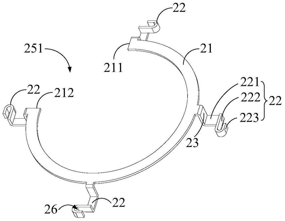
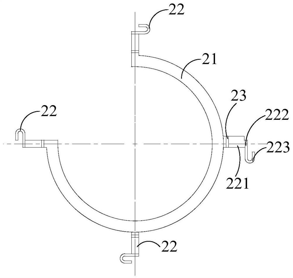
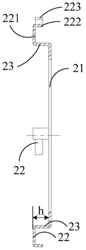
[0132] Each bus bar 2 includes an arc-shaped main body portion 21 and a plurality of connecting portions 22, such as Figure 1 to Figure 9 as well as Figure 13 and Figure 14 shown. Wherein, the main body part 21 is embedded in the framework 1 (such as Figure 19 and Figure 20 shown), and extend along the circumferential direction of the skeleton 1, such as figure 1 , figure 2 , Figure 4 , Figure 5 , Figure 7 , Figure 8 , Figure 13 and Figure 14 As shown; a plurality of connecting parts 22 are connected with the main body part 21 and protrude from the skeleton 1 (such as Figure 20 shown), and a plurality of connection parts 22 are evenly distributed along the circumferential direction of the main body part 21, and are used to connect the terminal 41 of the motor stat...

Embodiment 2

[0196] The difference from Embodiment 1 is that: on the basis of Embodiment 1, further, the end faces of the connecting parts 22 of all bus bars 2 away from the stator windings are kept flush in the axial direction of the skeleton 1, as Figure 18 and Figure 19 shown.

[0197] The end faces of all the connecting parts 22 away from the stator winding are kept flush in the axial direction of the frame 1 (that is: the end faces of all the connecting parts 22 away from the stator winding are located on the same plane perpendicular to the central axis of the frame 1), such as Figure 19 As shown, in this way, the terminals 41 of all windings can also be kept flush, and the same length is reserved. After the welding is completed, the excess wire ends are cut off at the same position, so as to achieve a high degree of consistency in the wiring operation, which is convenient for manual operation and It is easy to operate the machine, thus helping to significantly improve the product...

Embodiment 3

[0243] The difference from any of the above-mentioned embodiments is that: on the basis of any of the above-mentioned embodiments, further, the framework 1 includes a ring-shaped bracket 11 and a plurality of strip-shaped brackets 12 . Specifically, a plurality of strip brackets 12 are integrally connected with the ring bracket 11, such as Figure 23 shown. The main body portion 21 of all bus bars 2 is embedded in the annular bracket 11, such as Figure 21 to Figure 23 shown. A plurality of strip brackets 12 correspond to a plurality of terminals 3 one-to-one, such as Figure 20 As shown, and a part of each terminal 3 is embedded in the corresponding strip bracket 12, as Figure 23 and Figure 25 shown.

[0244] The framework 1 includes a ring-shaped support 11 and a strip-shaped support 12 . The ring bracket 11 is used to support multiple bus bars 2 and ensure mutual insulation between the multiple bus bars 2 . Multiple strip supports 12 are used to support multiple te...


PUM


Abstract

The invention provides a busbar, a motor and a vehicle. The busbar comprises a skeleton; a plurality of busbars, wherein each busbar comprises an arc-shaped main body part and a plurality of connecting parts, and all the busbars are divided into a neutral busbar and a plurality of phase busbars; a plurality of terminals respectively provided on the plurality of phase busbars; wherein the main bodyparts of the neutral busbars and the main body parts of the plurality of phase busbars are sequentially stacked and arranged in the axial direction of the framework and are separated from each otherat intervals, and the connecting parts of all the busbars are uniformly distributed in the circumferential direction of the framework. According to the scheme, the busbars can be quickly assembled, and the production efficiency of the busbars is improved.

Description

technical field [0001] The invention relates to the technical field of motors, in particular to a bus bar, a motor including the bus bar, and a vehicle including the motor. Background technique [0002] The motor stator generally has multiple windings, and each winding has two terminals, a start end and an end end. The start and end ends of different windings need to be connected to each other according to product requirements to ensure the normal operation of the motor. The wiring form is relatively complicated. It is not conducive to the fast and efficient operation of the production line and reduces the production efficiency of the product. Contents of the invention [0003] In order to solve at least one of the above technical problems, an object of the present invention is to provide a bus bar. [0004] Another object of the present invention is to provide a motor comprising the above-mentioned bus bar. [0005] Another object of the present invention is to provide ...

Claims


Application Information

Patent Timeline
IPC IPC(8): H01R13/02H01R25/16H02K3/28
CPCH01R13/02H01R25/161H01R25/162H01R2201/10H01R2201/26H02K3/28
Inventor 施涛徐浩扬孙国庆万佳葛笑
Owner ANHUI WELLING AUTO PARTS CO LTD
Why Eureka
Try Eureka