Diffractive biosensor
A biosensor and biological technology, applied in the field of diffractive biosensors, can solve problems such as inability to obtain measurement signals, and achieve the effect of improved measurement accuracy and large tolerance
- Summary
- Abstract
- Description
- Claims
- Application Information
AI Technical Summary
Problems solved by technology
Method used
Image

Examples
no. 1 approach
[0083] Figures 1 to 4 take two side view Figure X Z( figure 1 ) and YZ ( Figure 4 ) and to target components - biochips and light shields ( figure 2 ) and the shutter ( image 3 ) shows the first embodiment in plan view.
[0084] The light L of a coherent laser light source (not shown) is coupled into the planar waveguide W of the biochip BC arranged on the substrate SUB via an coupling-in grating EKG. Here, the substrate SUB having elements arranged on the front and back surfaces of the substrate SUB is referred to as a biochip BC. Together with other elements like light sources and detectors and a movable aperture and other elements a biosensor is obtained.
[0085] The wavelength of the coherent laser light source is preferably in the range of 400nm to 1000nm. The coupling-in grating EKG is located on the underside of the planar waveguide W. The light L coupled into the planar waveguide W propagates in the X direction (outside the waveguide X, the light mode dr...
no. 2 approach
[0095] Figures 5 to 9 take two side view Figure X Z( Figure 5 ) and YZ ( Figure 9 ) and to target components -- biochips ( Figure 6 ), visor ( Figure 7 ) and combined shutter / delay plate bracket ( Figure 8 ) shows a top view of a second embodiment of the invention.
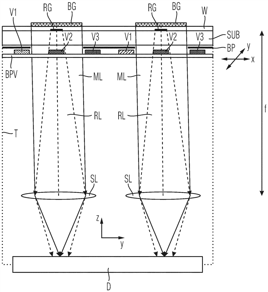
[0096] Only the differences from the first embodiment are described below. The reference grating RG now lies (in the z direction) below the associated biograting RG and there each a fraction of the light in the planar waveguide W is coupled out as a reference beam RL in the form of a spherical wave. For this purpose, the reference grating RG is implemented as a chirped grating with curved grating lines and acts as a diffractive emission lens. In contrast, the biograting BG is implemented as a linear grating with a constant grating period and couples the collimated measuring beam ML out of the waveguide W. In order to avoid reflections of the linear grating back into the planar waveguide W due to sec...
no. 3 approach
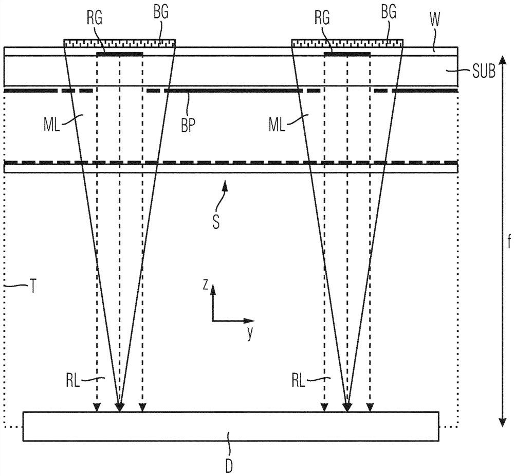
[0112] Figures 10 to 13 look sideways Figure X Z( Figure 10 ) and to the component--biochip waveguide ( Figure 11 ), the upper side of the mask with the reference grating waveguide ( Figure 12 ) and the underside of the visor ( Figure 13 ) shows a third embodiment in plan view. Only the differences from the first embodiment are described below.
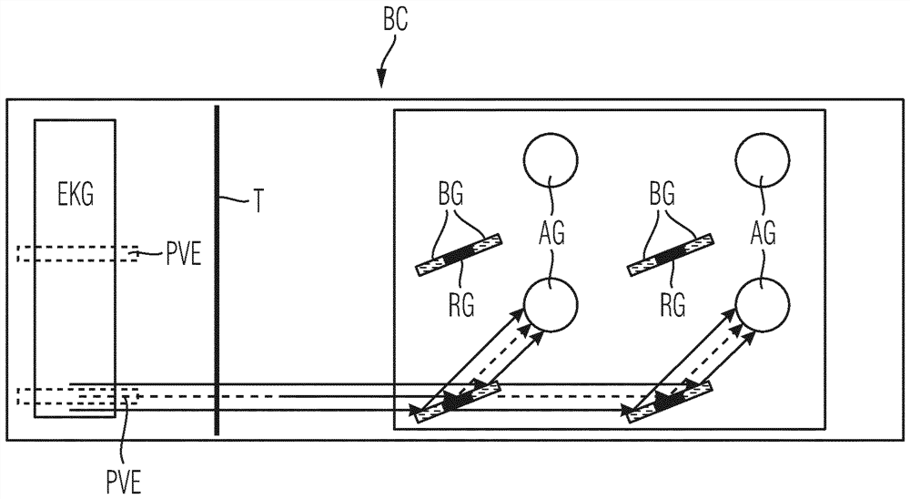
[0113] In this embodiment, the biograting BG is designed again as a diffractive lens and focuses the measuring beam ML onto the detector D again. The reference beam R passes through the mask BP. For this purpose, the bezel BP has a substrate SUB′, a coupling-in grating EKG and a separate planar waveguide W′. Part of the light L of a coherent laser light source (not shown) is phase-shifted via a liquid crystal element or an optoelectronic phase delay element PVE in the form of an optoelectronic modulator and coupled via an coupling-in grating EKG into the planar waveguide W' of the shutter BP. There the light propagates i...
PUM
 Abstract
Description
Claims
Application Information
 - R&D Engineer
- R&D Manager
- IP Professional
- Industry Leading Data Capabilities
- Powerful AI technology
- Patent DNA Extraction
Browse by: Latest US Patents, China's latest patents, Technical Efficacy Thesaurus, Application Domain, Technology Topic.
© 2024 PatSnap. All rights reserved.Legal|Privacy policy|Modern Slavery Act Transparency Statement|Sitemap