A device for shearing tree roots at curb stones

A shearing device and curbstone technology, applied in the direction of roads, roads, cutting tools, etc., can solve the problems of laborious cutting work and high toughness, and achieve the effect of reducing the difficulty of manual work and reducing the possibility of damage

Active Publication Date: 2022-05-06
SHANDONG UNIV OF SCI & TECH
View PDF5 Cites 0 Cited by
  • Summary
  • Abstract
  • Description
  • Claims
  • Application Information

AI Technical Summary

Problems solved by technology

Because the tree roots here are all living bodies, their toughness is relatively high, and the work of excision is also extremely laborious.

Method used


Image

  • A device for shearing tree roots at curb stones
  • A device for shearing tree roots at curb stones
  • A device for shearing tree roots at curb stones

Examples


Embodiment 1

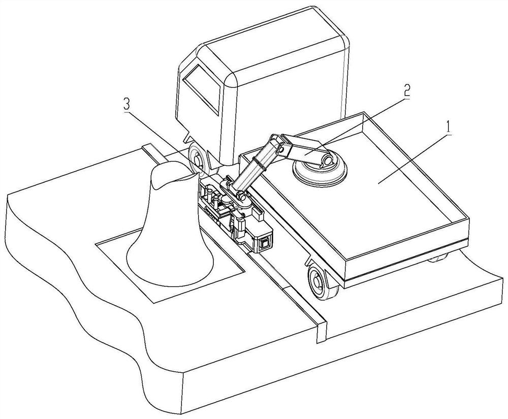
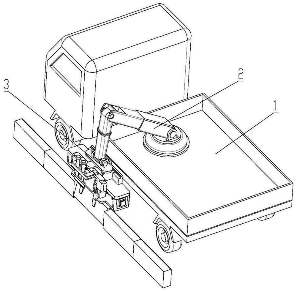
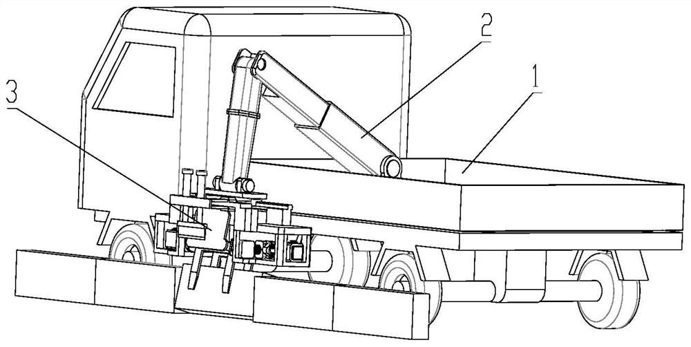
[0046] see Figure 1 to Figure 7 , the present invention provides a cutting device for tree roots at curbstones, comprising a main support 31, the main support 31 is connected to a clamping assembly 32 and a shearing assembly 33;

[0047] The clamping assembly 32 includes a fixed splint 321 and a movable splint 322, and both sides of the fixed splint 321 are rotatably connected to the main bracket 31;

[0048] The cutting assembly 33 is arranged on the side of the tree when the device works, and the cutting assembly 33 includes a cutter 331, the upper side of the cutter 331 is fixedly connected to the movable end of the cutter push rod 332, and the fixed end of the cutter push rod 332 It is fixedly connected with the cutter bracket 333; the cutter bracket 333 is connected with the main bracket 31.

[0049] When this device is applied, it can be combined with the existing vehicle body 1 and the mechanical arm 2, and the shearing device 3 is connected to the end of the mechanic...

Embodiment 2

[0056] see Figure 8 to Figure 10 , on the basis of Embodiment 1, the outer side of the rotating shaft of the fixed splint 321 is sleeved with a limit ring 311, and the limit ring 311 is rotationally connected with the rotating shaft;

[0057] The limiting ring 311 is fixedly connected with the vibrating block 312. The side adjacent to the limiting ring 311 on the vibrating block 312 is fixedly provided with a vibrating rod 313. The axis of the vibrating rod 313 is perpendicular to the axis extension line of the limiting ring 311. The vibrating rod 313 runs through the limiting plate 314 and is slidably connected with the limiting plate 314. The limiting plate 314 is fixedly arranged on the lower support plate 315. The lower support plate 315 is a fixed part of the main support 31. One end of the vibrating rod 313 is fixed to the vibrating block 312. connected, the other end is fixedly connected to the vibrating plate 316; a vibrating spring 317 is arranged between the limitin...

Embodiment 3

[0064] see Figure 11 to Figure 15 , on the basis of the above embodiment, the side of the fixed splint 321 away from the movable splint 322 is fixedly connected to the supporting plate 325 through the connecting rod, and the supporting plate 325 extends toward the middle part of the fixed splint 321 away from the side of the two parallel parts;

[0065] When the device is in the cut-off state, the supporting plate 325 is horizontal, and the supporting plate 325 is located below the cutting knife 331 .

[0066] The weight of the parallel parts of the fixed splint 321 and the movable splint 322 is greater than that of the supporting plate 325 , and in a natural state, the supporting plate 325 is positioned upward.

[0067] The supporting plate 325 can support the tree roots from the lower side during the cutting operation, because the tree roots themselves have toughness, if only a cutting force is applied from the top, the roots will be pressed down, and it is difficult to com...


PUM


Abstract

The invention discloses a cutting device for tree roots and hairs at curbstones, which relates to the field of electromechanical control equipment. The technical proposal includes a main bracket connected to a clamping assembly and a shearing assembly; the clamping assembly includes a fixed splint and a movable splint , both sides of the fixed splint are rotatably connected with the main bracket; the shearing assembly is set on the side facing the tree when the device is working, the shearing assembly includes a cutter, the upper side of the cutter is fixedly connected to the movable end of the cutter push rod, and the cutting The fixed end of the knife push rod is fixedly connected with the cutter support; the cutter support is connected with the main support. The beneficial effect of the present invention is that the device can realize the extraction of curbstones and the cutting of redundant roots of trees by means of machines, thereby greatly reducing the difficulty of manual work. Through the specific clamping components, the curb stone can be taken out by shaking in the clamped state, which reduces the possibility of damage caused by the curb stone being forcibly removed.

Description

technical field [0001] The invention relates to the field of electromechanical control equipment, in particular to a cutting device for tree roots at curbstones. Background technique [0002] Tree planting is an important part of urban greening. Generally speaking, trees are planted on the sidewalks on both sides of the road, and the planting position of the trees is usually close to the curbstone. As the roots grow, the roots will extend by themselves, and often the roots will squeeze and deform the curb, causing the curb to tilt towards the direction of the road. For this problem, it is all repaired manually at present, and the curb stone needs to be taken out first. Since the curb stone is installed with mortar at the bottom, the process of manual removal is relatively laborious. After the curb stone is removed, it is necessary to manually remove the redundant tree roots with a shovel or a knife. Because the tree roots here are all living bodies, their toughness is rela...

Claims


Application Information

Patent Timeline
Patent Type & Authority Patents(China)
IPC IPC(8): A01G3/00E01C23/06
CPCA01G3/08E01C23/06
Inventor 祝长生安新军张成元刘玉兰刘华
Owner SHANDONG UNIV OF SCI & TECH
Why Eureka
Try Eureka