Construction site steel bar bending equipment for construction
A construction and construction site technology, which is applied in the field of steel bar bending equipment for construction sites, can solve the problems of affecting work progress, unfavorable migration work, and huge equipment, and achieve the effect of high-efficiency bending
- Summary
- Abstract
- Description
- Claims
- Application Information
AI Technical Summary
Problems solved by technology
Method used
Image

Examples
Embodiment 1
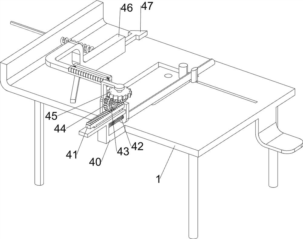
[0031] A construction site steel bar bending equipment, such as figure 1 , figure 2 , image 3 , Figure 4 , Figure 5 , Figure 6 and Figure 7 As shown, it includes a mounting frame 1, a servo motor 2, a bending mechanism 3, a propulsion mechanism 4, and a lowering mechanism 5. The servo motor 2 is provided on the left side of the mounting frame 1, and two fixing columns are provided on the front side of the top of the mounting frame 1. The installation frame 1 is provided with a bending mechanism 3 , the installation frame 1 is provided with a propulsion mechanism 4 , and the bending mechanism 3 is provided with a lowering mechanism 5 .
[0032] When people need to use this equipment, first people place the steel bar between the fixed columns, then start the servo motor 2, the servo motor 2 drives the bending mechanism 3 to operate, and then makes the bending mechanism 3 move to the right, and the bending mechanism 3 is ready to be bent When the mechanism 3 is in con...
Embodiment 2
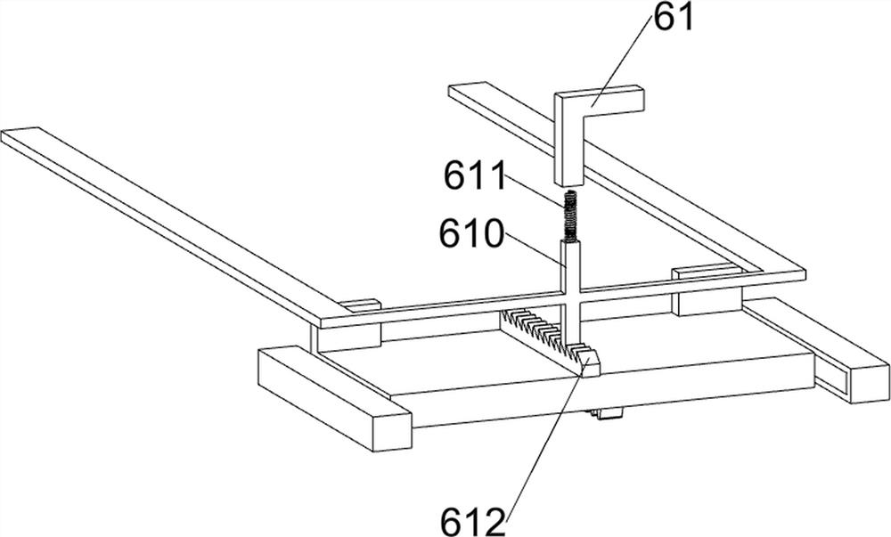
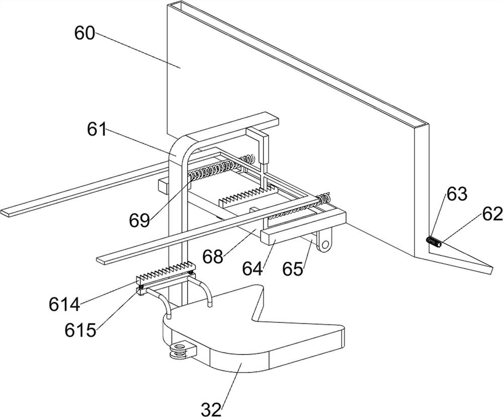
[0040] On the basis of Example 1, such as figure 1 , Figure 8 , Figure 9 , Figure 10 and Figure 11 As shown, it also includes a blanking mechanism 6. The mounting frame 1 is provided with a blanking mechanism 6. The blanking mechanism 6 includes a material box 60, a support plate 61, a third rotating rod 62, a second torsion spring 63, and a second slide rail. 64. Rotating shaft 65, third ratchet gear 66, second missing gear 67, ejector block 68, ninth spring 69, block 610, tenth spring 611, third ratchet rack 612, third long rack 613, The fourth ratchet bar 614 and the eleventh spring 615, the left side of the top of the installation frame 1 is provided with a support plate 61, the right side of the support plate 61 is provided with a material box 60, and the bottom of the material box 60 right side is rotatably provided with a third rotating rod 62 Spring, the second torsion spring 63 is provided between both ends of the third rotating rod 62 and the material box 60,...
PUM
 Abstract
Description
Claims
Application Information
 - Generate Ideas
- Intellectual Property
- Life Sciences
- Materials
- Tech Scout
- Unparalleled Data Quality
- Higher Quality Content
- 60% Fewer Hallucinations
Browse by: Latest US Patents, China's latest patents, Technical Efficacy Thesaurus, Application Domain, Technology Topic, Popular Technical Reports.
© 2025 PatSnap. All rights reserved.Legal|Privacy policy|Modern Slavery Act Transparency Statement|Sitemap|About US| Contact US: help@patsnap.com