
Steel bar surface cleaning device applied to concrete construction

A surface cleaning and concrete technology, applied in the field of construction, can solve the problems of water waste, liquid splashing, time-consuming and labor-consuming, etc., and achieve the effect of improving work efficiency and fixing firmly

Active Publication Date: 2021-03-02
安徽裕祥建筑科技有限公司
View PDF7 Cites 0 Cited by
  • Summary
  • Abstract
  • Description
  • Claims
  • Application Information

AI Technical Summary

Problems solved by technology

Generally, some steel bars are piled up for use on large construction sites, but if the steel bars are exposed to the outdoors for a long time and are affected by rain and humid air, floating rust will form on the surface
If the floating rust on the surface of the steel bar is not cleaned, it will affect the bond between the concrete and the steel bar, affect the bearing capacity and durability of the reinforced concrete, and pose a threat to the safety of the building
[0003] However, most of the traditional methods for removing floating rust on the surface of steel bars are that construction personnel use high-pressure water guns to stamp steel bars. When the operator puts the steel bar into the solvent or takes it out, the gravity of the steel bar may cause the liquid to splash out, and then touch the human skin; in addition, if the steel bar is not fixed firmly, it may be scattered when it enters the solution, causing the operator to be insecure. Easy access, which in turn hinders operator productivity

Method used


Image

  • Steel bar surface cleaning device applied to concrete construction
  • Steel bar surface cleaning device applied to concrete construction
  • Steel bar surface cleaning device applied to concrete construction

Examples


Embodiment Construction

[0018] The following will clearly and completely describe the technical solutions in the embodiments of the present invention with reference to the accompanying drawings in the embodiments of the present invention. Obviously, the described embodiments are only some, not all, embodiments of the present invention. Based on the embodiments of the present invention, all other embodiments obtained by persons of ordinary skill in the art without making creative efforts belong to the protection scope of the present invention.

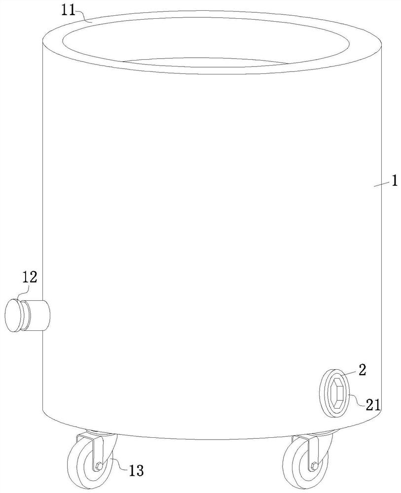
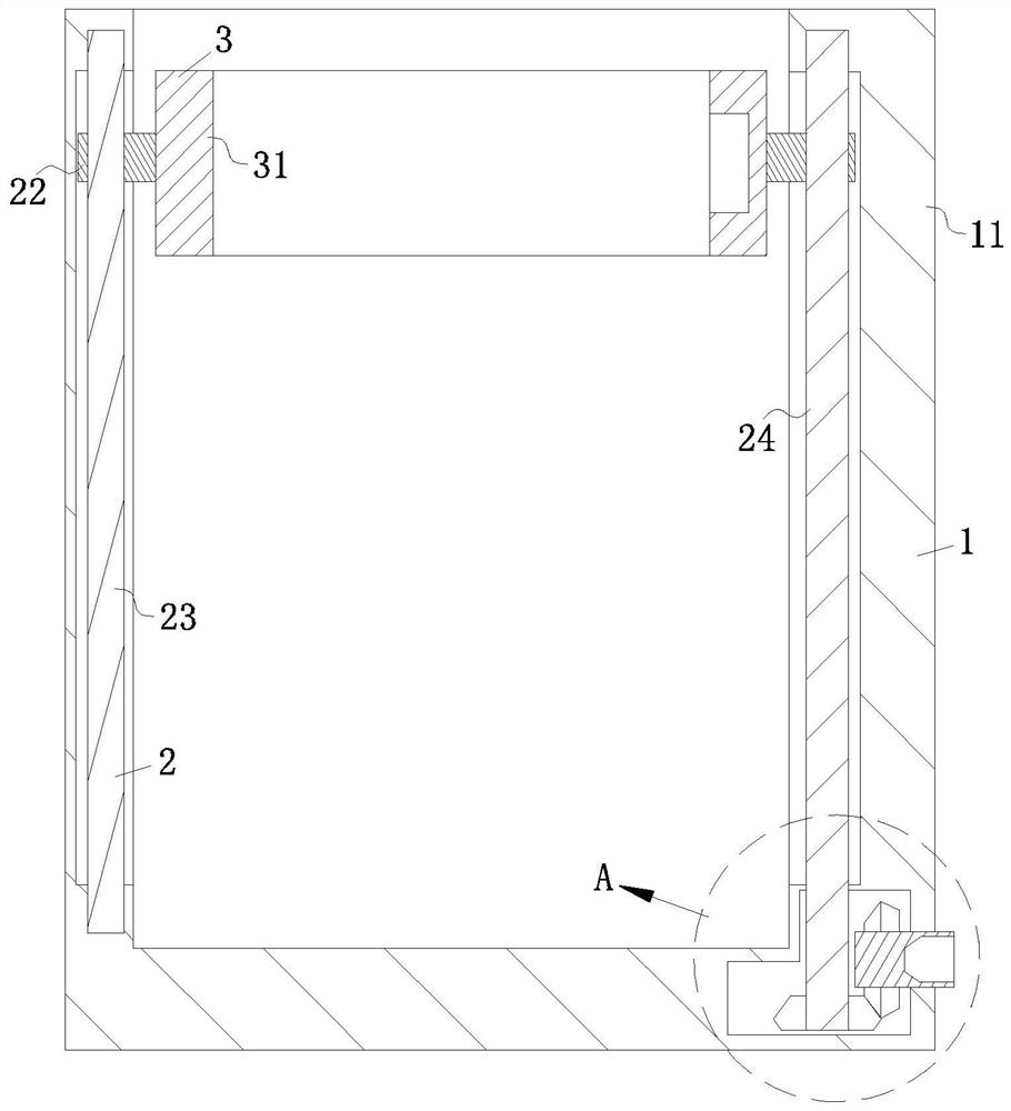
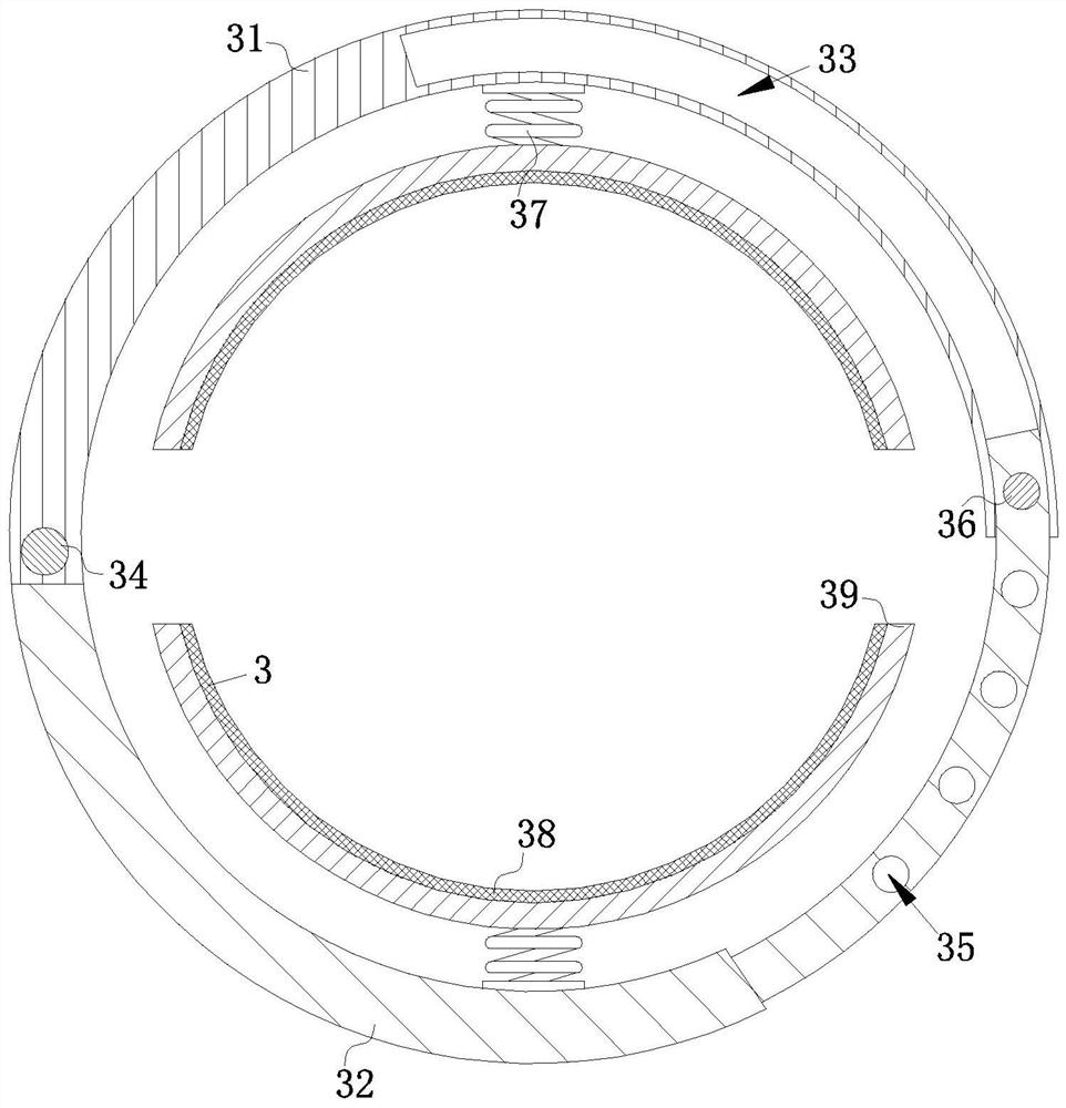
[0019] see Figure 1-4 As shown, a steel bar surface cleaning device for concrete construction includes a main body mechanism 1, the bottom end side wall of the main body mechanism 1 is rotatably connected with a driving mechanism 2, and the driving mechanism 2 is fixedly connected with the fixing mechanism 3. The fixing mechanism 3 includes a first snap ring 31, a second snap ring 32, a chute 33, a guide shaft 34, a limit groove 35, a screw 36, two telescopic...


PUM


Abstract

The invention discloses a steel bar surface cleaning device applied to concrete construction. The steel bar surface cleaning device comprises a main body mechanism, a driving mechanism, a fixing mechanism, a first clamping ring, a second clamping ring, a sliding groove, a guide shaft, a limiting groove, a screw, a telescopic spring and a fixing ring. The steel bar cleaning device disclosed by theinvention has the beneficial effects that one end of the second clamping ring rotates with the first clamping ring; the other end of the second clamping ring slides in the sliding groove in the innerwall of the first clamping ring; the screw is in threaded connection with the limiting groove in the end part of the second clamping ring after penetrating through the first clamping ring; the telescopic spring is fixed to the inner walls of the first clamping ring and the second clamping ring; a fixing ring and the telescopic spring are fixed together; steel bars are placed in a gap between the first clamping ring and the second clamping ring; the second clamping ring is extruded; the screw is in threaded connection with the limiting groove, so that the steel bars are fixed between the firstclamping ring and the second clamping ring while the fixing ring is applied with a force; and thus the telescopic spring is extruded to ensure that the steel bars are fixed more firmly; the steel barsare prevented from being scattered after being soaked into a solution, thus people can take the steel bars conveniently, and the work efficiency of an operator is improved.

Description

technical field [0001] The invention relates to a cleaning device, in particular to a steel bar surface cleaning device for concrete construction, which belongs to the technical field of building construction. Background technique [0002] Rebar refers to steel for reinforced concrete and prestressed reinforced concrete. Generally, some steel bars are piled up for use in large-scale construction sites. However, if the steel bars are exposed to the outdoors for a long time and are affected by rain and humid air, floating rust will form on the surface. If the floating rust on the surface of the steel bar is not cleaned, it will affect the bond between the concrete and the steel bar, affect the bearing capacity and durability of the reinforced concrete, and pose a threat to the safety of the building. [0003] However, most of the traditional methods for removing floating rust on the surface of steel bars are that construction personnel use high-pressure water guns to stamp st...

Claims


Application Information

Patent Timeline
IPC IPC(8): C23G3/00
CPCC23G3/00
Inventor 毛祖顺
Owner 安徽裕祥建筑科技有限公司
Learn More