
Camber control method based on slab center line deviation analysis

A control method and camber technology, applied in the field of control, can solve the problems that the bouncing data cannot be very accurate, the influence of control is not considered, and the stiffness test cannot be done, so as to reduce adverse effects, reduce the degree of bending, and improve the degree of camber Effect

Active Publication Date: 2021-03-05
BAOSHAN IRON & STEEL CO LTD
View PDF16 Cites 0 Cited by
  • Summary
  • Abstract
  • Description
  • Claims
  • Application Information

AI Technical Summary

Problems solved by technology

[0012] In the above technical solutions, patents (1) and (2) are based on the actual values ​​of the rolling force on both sides of the horizontal roll, the roll gap, and the bounce of the rolling mill to calculate the horizontal roll One-sided or double-sided roll gap adjustment; the disadvantage is that the rolling mill stiffness is used in the calculation of rolling mill bounce, and rough rolling usually uses electric pressing, so stiffness testing cannot be done, so it is not necessary to obtain very accurate stiffness data. Too realistic, resulting in calculated bounce data cannot be very accurate
The disadvantage of this method is that the risk of correcting the camber through the side guide plate is extremely high, and it is easy to cause steel jamming.
The disadvantage is the same as the patent (1) (2), the stiffness calculation is not accurate
Patent (5) calculates the length of both sides of the slab, calculates the difference in extension on both sides, and calculates the camber adjustment amount through model calculation. This method is relatively complicated to calculate, and does not consider the camber control of the slab reduction and slab width. Impact

Method used


Image

  • Camber control method based on slab center line deviation analysis
  • Camber control method based on slab center line deviation analysis
  • Camber control method based on slab center line deviation analysis

Examples


Embodiment

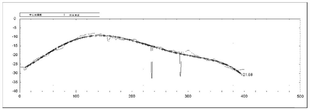
[0100] Assume that the centerline deviation data measured according to step 1) and step 2) are as follows Figure 5As shown in , all the data are fitted with a quadratic polynomial, and the fitted data result is:

[0101] y=-0.0012752x 2 +0.65984x-79.7912

[0102] Since its quadratic coefficient -0.0012752 is less than 0, the parabola opens downward.

[0103] Assume that opening up means the head is bent towards the driving side and opening down means the head is bent towards the operating side. Then the opening of this slab is downward, which means that the head is bent to the operation side, so the operation side should be pressed more accordingly. The actual pressure needs to be calculated according to the degree of bending.

[0104] Use a 5th degree polynomial to fit the curve. The fitted curve can effectively filter abnormal data. For the fitted curve represented by the "+" curve in the figure, the equation after the 5th degree polynomial fitting is as follows:

[01...


PUM


Abstract

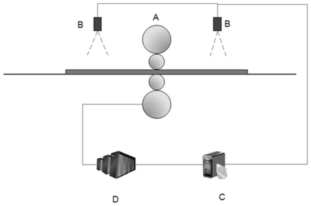
The invention discloses a camber control method based on slab center line deviation analysis, and belongs to the field of control. The camber control method comprises the following steps: installing camber measuring instruments in front of and behind a reciprocating rolling mill respectively; adopting the camber measuring instruments for detecting a slab center line curve; judging a bending direction and a bending degree according to the central line deviation data curve; calculating a roll gap correction amount; correcting the roll gap correction amount according to the current pass width andthe rolling reduction; and adopting L1 to adjust the roll gap difference between the two sides of a horizontal roll according to the roll gap correction amount data, and carrying out rolling in the subsequent pass on this basis so as to realize automatic feedback type control over the camber. According to the camber control method, by analyzing the deviation data of the center line of the rolledslab, the set value of the roll gap difference between the two sides of the horizontal roll in the subsequent pass is automatically calculated, so that the camber bending degree is reduced, the straightness of the slab is ensured, the labor intensity of rough rolling operators is reduced, and the automation rate of rough rolling production is increased. The camber control method can be widely applied to the field of process control of slabs in the rolling process.

Description

technical field [0001] The invention belongs to the field of control, and in particular relates to a method for improving the camber degree in the slab rolling process and ensuring the straightness of the slab in the length direction after rough rolling. Background technique [0002] The camber of the slab after rolling is mainly due to the asymmetric deformation during rolling. [0003] The main factors causing asymmetric deformation include: temperature distribution in the width direction of the slab, execution accuracy of the rolling mill, thickness difference between the two sides in the width direction of the slab, actual centering accuracy of the slab, etc. The camber of the slab is the result of the combination of these factors. [0004] The difficulty in controlling slab camber mainly lies in the fact that there are many influencing factors, and some data in these influencing factors are unmeasurable or difficult to measure accurately. For example: the temperature ...

Claims


Application Information

Patent Timeline
Patent Type & Authority Applications(China)
IPC IPC(8): B21B37/30
CPCB21B37/30
Inventor 沈际海张健民吴海飞
Owner BAOSHAN IRON & STEEL CO LTD
Learn More