Roller synchronous feeding device

A technology of feeding device and material guiding device, applied in the direction of feeding device, positioning device, storage device, etc., can solve the problems of small force, sheet bending, and large force, etc.

Inactive Publication Date: 2014-12-24
重庆腾田科技发展有限公司
View PDF0 Cites 3 Cited by
  • Summary
  • Abstract
  • Description
  • Claims
  • Application Information

AI Technical Summary

Problems solved by technology

Existing plate conveying devices usually include a driving roller driven by a motor and a driven roller matching the driving roller, wherein the driven roller is only connected to the frame in rotation, and the driving force of the plate mainly comes from the fric

Method used


Image

  • Roller synchronous feeding device
  • Roller synchronous feeding device

Examples


Embodiment 1

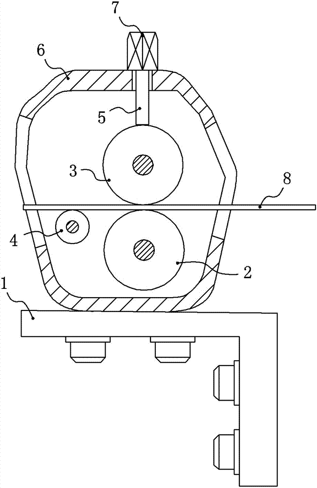
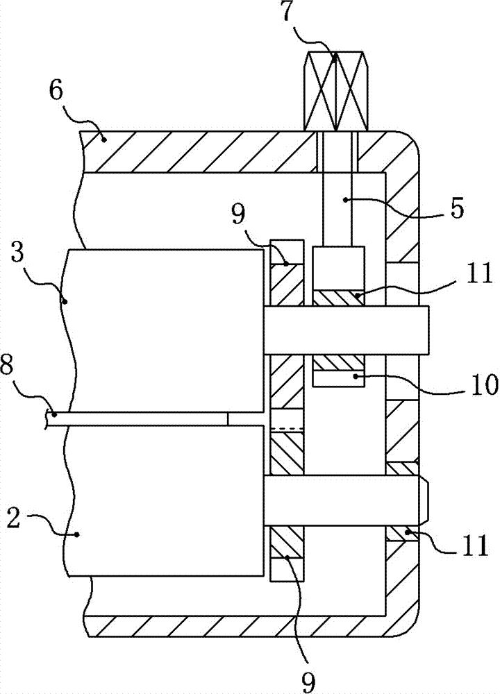
[0013] like figure 1 As shown, a shaft-roller synchronous feeding device includes a frame 1, a casing 6, a driving roller 2 and a driven roller 3, the casing 6 is installed on the frame 1 through bolts, and the casing 6 is provided with a feeding port And the discharge port, the driving roller 2 is driven by a motor, and the driving roller 2 is located under the driven roller 3. In this embodiment, the motor is a commonly used ordinary motor. 6 connections such as figure 2 As shown, an adjustment mechanism is also provided. The adjustment mechanism includes an adjustment rod 5, an adjustment nut 7 and an adjustment seat 10. Both sides of the driven roller 3 are provided with an adjustment mechanism. The adjustment seat 10 is connected, the adjustment rod 5 is fixedly connected with the adjustment seat 10, and the adjustment rod 5 vertically penetrates the upper part of the housing 6, the adjustment nut 7 is threaded with the upper end of the adjustment rod 5, and the adjustm...

Embodiment 2

[0017] Different from Embodiment 1, the material guide device is a guide wheel located on both sides of the plate 8, and the guide plane formed by the guide wheels on both sides is equal to the upper surface of the driving roller 2, and the guide wheels on both sides can limit the vertical direction of the plate 8. The deviation in the direction and horizontal direction, and the plate 8 can enter between the driving roller 2 and the driven roller 3 straightly.

[0018] Specific workflow:

[0019] like figure 1 As shown, first adjust the adjustment mechanism on both sides of the driven roller 3 according to the thickness of the plate 8, and then adjust the adjustment nut 7, the driven roller 3 can move vertically, and adjust to the alignment between the driving roller 2 and the driven roller 3. 8 After extrusion, start the motor, and the motor drives the driving roller 2 to rotate, such as figure 2 As shown, since the driving roller 2 and the driven roller 3 are respectively...


PUM


Abstract

The invention belongs to the field of feeding of workpieces related to stroke of dies or tools, and particularly relates to a roller synchronous feeding device. The device comprises a machine frame, a shell, a driving roller and a driven roller. The shell is arranged on the machine frame, the driving roller is driven by a motor, and the two ends of the driving roller are connected with the shell through bearings. The roller synchronous feeding device further comprises adjusting mechanisms, each adjusting mechanism comprises an adjusting rod, an adjusting nut and an adjusting base, the two sides of the driven roller are respectively provided with one adjusting mechanism, the two sides of the driven roller are connected with the adjusting bases of the adjusting mechanisms through bearings, the adjusting rods are connected with the adjusting bases, and ascending and descending of the adjusting bases are controlled through matching of the adjusting nuts; the driving roller and the driven roller are respectively provided with a gear, and the gears are meshed. In the roller synchronous feeding device, stress on the upper side of a conveyed plate and stress on the lower side of the conveyed plate are approximately equal, so that it is guaranteed that the conveyed plate is flat and straight.

Description

technical field [0001] The invention belongs to the field of workpiece feeding related to mold or tool stroke, and in particular relates to a shaft-roller synchronous feeding device. Background technique [0002] During sheet material processing, in order to achieve continuous processing, it is usually necessary to realize continuous feeding through a special sheet material conveying device. The existing sheet material conveying device conveys through the friction force between the roller and the sheet material. Existing plate conveying devices usually include a driving roller driven by a motor and a driven roller matching the driving roller, wherein the driven roller is only connected to the frame in rotation, and the driving force of the plate mainly comes from the frictional force on the plate during the rotation of the driving roller. The force on the side of the plate that contacts the driving roller is large, and the force on the side that is in contact with the driven...

Claims


Application Information

Patent Timeline
IPC IPC(8): B21D43/09
Inventor 包俊
Owner 重庆腾田科技发展有限公司
Why Eureka
Try Eureka