Stationary phase radio frequency cable shielding layer cutting device

A technology for radio frequency cables and cutting devices, which is applied to the equipment, circuits, electrical components and other directions of dismantling/armoring cables, can solve the problem that the manual cutting method is difficult to meet the requirements of the cutting section, and achieves a simple structure, the cutting section is satisfactory, and the guarantee The effect of precision

Active Publication Date: 2013-12-11
CHENGDU SIWI HIGH TECH IND GARDEN
View PDF5 Cites 7 Cited by
  • Summary
  • Abstract
  • Description
  • Claims
  • Application Information

AI Technical Summary

Problems solved by technology

[0006] The purpose of the present invention is to provide a cutting device for phase-stable radio frequency cable shielding layer, which is used for finely adjusting and cutting the cable shielding layer when phase inconsistency occurs in the assembly and testing process of phase-stable cable assemblies. Difficult to achieve the technical problem of cutting section requirements, which can effectively solve the problems existing in the above-mentioned prior art

Method used


Image

  • Stationary phase radio frequency cable shielding layer cutting device
  • Stationary phase radio frequency cable shielding layer cutting device
  • Stationary phase radio frequency cable shielding layer cutting device

Examples


Embodiment 1

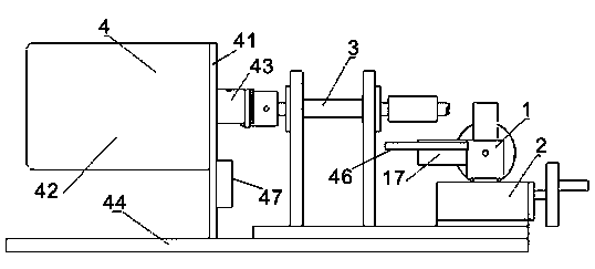
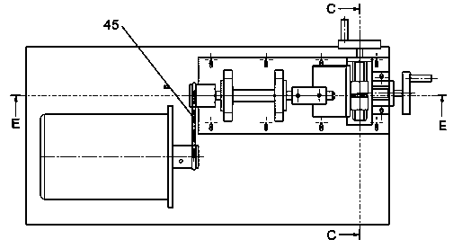
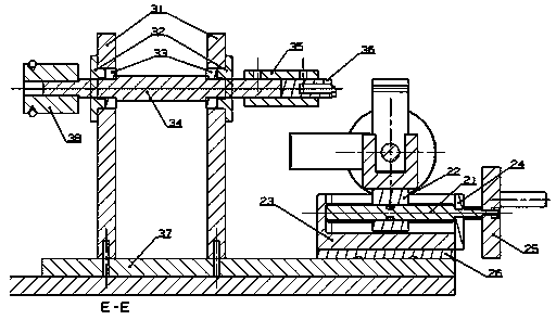
[0031] Such as figure 1 , figure 2 , image 3 , Figure 4 As shown, a phase-stable RF cable shield cutting device includes a clamping module 1 , a feeding module 2 , a transmission bracket module 3 and a power module 4 . Its specific structure is as follows:

[0032] The clamping module 1 comprises a left clamping block 11, a right clamping block 12, a two-way screw rod 13, and a track groove 14. The bottoms of the left clamping block 11 and the right clamping block 12 are placed in the track groove 14, and the two-way spiral Rod 13 vertically passes through the bottom of left clamping block 11 and right clamping block 12, and the top of two-way screw rod 13 passes track groove 14, ends in track groove baffle plate 15; Described two-way screw rod 13 passes track The top of the groove 14 is provided with a clamping rotating hand wheel 16 . Bores are opened at the bottom of the left clamping block 11 and the right clamping block 12, and threads are installed in the holes, ...


PUM


Abstract

The invention discloses a stationary phase radio frequency cable shielding layer cutting device which comprises a clamping module, a feeding module, a transmission support module, and a power module. The clamping module comprises a left clamping block, a right clamping block, a double-direction screw rod, and a rail groove. The bottom of the left clamping block and the bottom of the right clamping block are arranged in the rail groove. The double-direction screw rod vertically penetrates through the bottom of the left clamping block and the bottom of the right clamping block. The top of the double-direction screw rod penetrates through the rail groove and abuts against the inside of a baffle of the rail groove. The feeding module comprises a feeding screw rod, a sliding block, and a feeding rail groove. The sliding block is fixed with the bottom of the rail groove of the clamping module. The feeding screw rod vertically penetrates through the sliding block with inner threads. The top of the feeding screw rod penetrates through the rail groove, and the two ends of the top of the feeding screw rod abut against the inside of a baffle of the feeding rail groove. The feeding screw rod rotates to drive the sliding block to drive the clamping module to be in transverse forward or backward linear motion. In the utilization process, the stationary phase radio frequency cable shielding layer cutting device can ensure the straightness of the cutting section of a cable and ensure cutting accuracy.

Description

Technical field [0001] The present invention involves cutting device, especially for a precision cutting device for stable -phase radio frequency cable components during the assembly process of stabilizing radio frequency cable components, which belongs to the field of cable shield cutting technology. [0002] Background technique [0003] In the cable -side operation regulations, there are a large number of conductive layers such as cable protective layers / insulating layers / shielding layers and non -conductive layers. The quality of the cutting quality has an important impact on the quality of the cable side connection.At present, the majority of the above cutting work is carried out by hand -rotating cutting by one -sided blade. The quality of the cutting quality has a lot to do with the technical level and experience of the cable side.Poor flatness, difficulty cutting quality, and other problems, and the cutting efficiency is not high. [0004] During the assembly process of s...

Claims


Application Information

Patent Timeline
Patent Type & Authority Applications(China)
IPC IPC(8): H02G1/12H01R43/28
Inventor 刘世忠周小飞
Owner CHENGDU SIWI HIGH TECH IND GARDEN
Why Eureka
Try Eureka