Check patentability & draft patents in minutes with Patsnap Eureka AI!

Embroidery machine thread hooking device capable of automatically adjusting thread quantity

A self-adjusting and machine thread catcher technology, applied in embroidery machines, embroidery machine mechanisms, sewing equipment, etc., can solve problems such as insufficient optimization, and achieve the effects of stable operation, reduced wool, and stable tightening.

Pending Publication Date: 2021-03-05
浙江镨美科智能刺绣设备有限公司
View PDF3 Cites 2 Cited by
  • Summary
  • Abstract
  • Description
  • Claims
  • Application Information

AI Technical Summary

Problems solved by technology

In this existing design, the upper thread trimming operation is controlled by controlling the movement of the embroidery material frame. Although the ability to control the consistency of the length has been improved, the length of the thread end after thread trimming and the collection of thread knots cannot be controlled. The control of tightness and thread trimming quality is not optimized enough

Method used


Image

  • Embroidery machine thread hooking device capable of automatically adjusting thread quantity
  • Embroidery machine thread hooking device capable of automatically adjusting thread quantity
  • Embroidery machine thread hooking device capable of automatically adjusting thread quantity

Examples


Embodiment 1

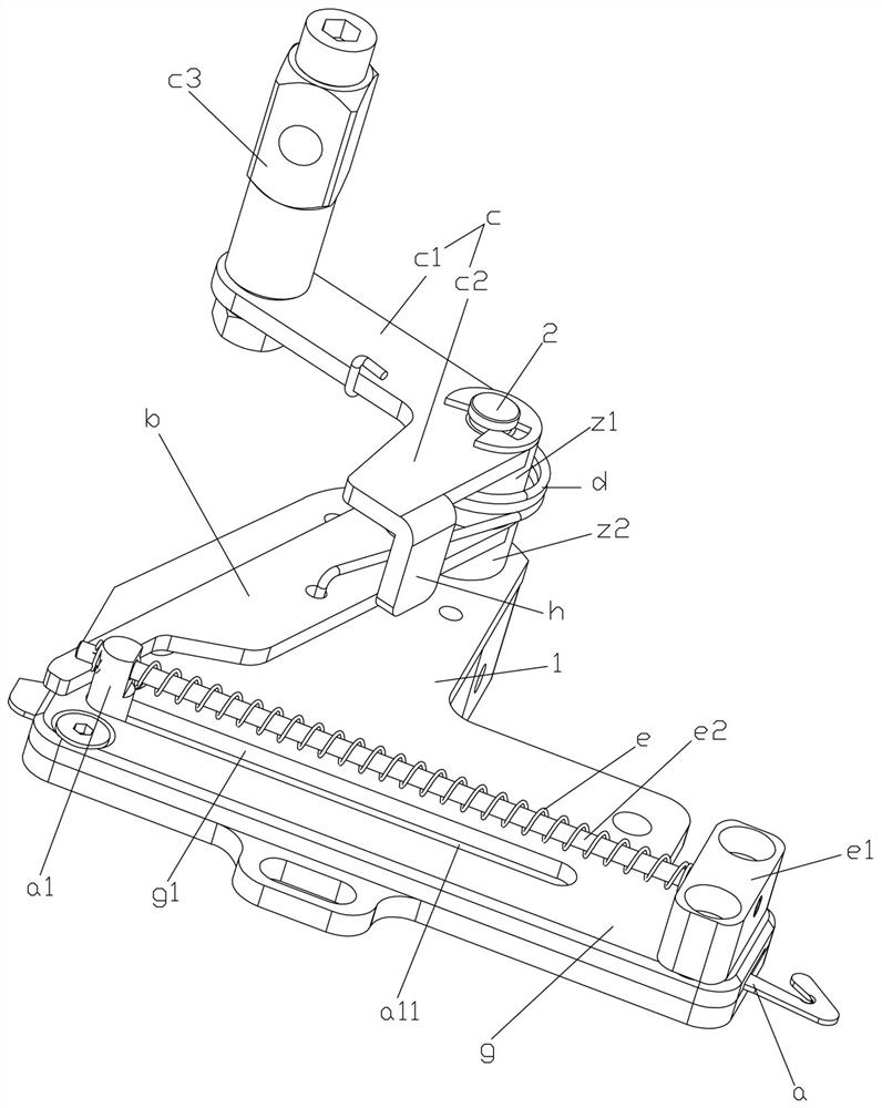
[0033] Example 1, such as Figure 1-3 As shown, an embroidery machine thread hooker capable of self-adjusting the amount of threads includes a base plate 1, a thread hook knife a mounted on the base plate 1, and a lower part for driving the thread hook knife a to move forward and out of the knife. The shift fork b and the upper shift fork c used to drive the lower shift fork b to swing back and forth between the front and rear, the base plate 1 is used as the basic component of the entire wire catcher to carry and install various components. Of course, the base plate 1 itself also needs Installed on the support structure in the machine head of the embroidery machine, so some installation holes also need to be opened. This is a conventional structure, which will not be described in detail here. In addition, after the substrate 1 is installed on the embroidery machine, it is usually preferred to be inclined forward and downward. The state is appropriate, and it is advisable to m...

Embodiment 2

[0046] Example 2, such as Figure 4-6 As shown, the difference between it and Embodiment 1 lies in the specific structural design of the elastic adjustment device, that is, the second structural style of the two preferred modes mentioned in Embodiment 1. Specifically, the spring e is a tension spring, except for this tension spring Stretching the spring, the elastic adjustment device also includes a spring stretching fit structure for stretching the spring e to form an elastic force, the spring stretch fit structure is to enable the spring to pull out the knife when hooking the thread knife and adjust the amount of thread In the process, the structure of the guide post a1 can be designed to position the rear part of the spring behind the guide post a1, so as to achieve the effect of stretching, but other structures that can make the spring stretch to form an elastic force are not excluded. This implementation A structure is introduced in , specifically, the spring tension fit ...


PUM


Abstract

The invention relates to the technical field of embroidery machine equipment, in particular to an embroidery machine thread hooking device capable of automatically adjusting thread quantity. The embroidery machine thread hooking device comprises a base plate, a thread hooking knife arranged on the base plate, a lower shifting fork used for driving the thread hooking knife to move back and forth, and an upper shifting fork used for driving the lower shifting fork to swing back and forth between front and back, wherein the upper shifting fork and the lower shifting fork are both arranged on a positioning shaft installed and connected to the base plate in a sleeving mode; a driving torsion spring is installed and connected between the upper shifting fork and the lower shifting fork; and the thread hooking knife is further connected with an elastic adjusting device for automatically tightening an upper thread, the thread quantity can be automatically adjusted, and the thread shearing effect is better.

Description

technical field [0001] The invention relates to the technical field of embroidery machine equipment, in particular to an embroidery machine thread catcher capable of self-adjusting the amount of thread. Background technique [0002] There are many types of embroidery machines, but most of them need to be equipped with corresponding hooking devices, because when the embroidery finishes one graphic unit, it needs to embroider another graphic unit or when changing colors, it needs to adjust the surface under the embroidery material. The thread and bobbin thread are trimmed. In the thread trimming process, mechanical structures such as the hook knife and the hooking rod device for driving the hook knife are needed. That is to say, the thread hooking device is needed to hook the thread to complete the thread trimming process. [0003] For example, the Chinese patent application number 02239633.0 discloses a multi-head computerized embroidery machine collective thread hooking mech...

Claims


Application Information

Patent Timeline
IPC IPC(8): D05C11/16D05C11/22
CPCD05C11/16D05C11/22
Inventor 陈天龙方狄永吴帆
Owner 浙江镨美科智能刺绣设备有限公司
Features
  • R&D
  • Intellectual Property
  • Life Sciences
  • Materials
  • Tech Scout
  • Unparalleled Data Quality
  • Higher Quality Content
  • 60% Fewer Hallucinations
Learn More