
Fabricated wall panel sliding assembly

A technology of sliding components and wall panels, which is applied in the field of architectural decoration, can solve the problems of bumping into patients, affecting the space inside the suite, danger, etc., and achieves the effects of easy cleaning, ingenious structural design, and beautiful decoration

Pending Publication Date: 2021-03-05
ZHEJIANG YASHA DECORATION
View PDF0 Cites 0 Cited by
  • Summary
  • Abstract
  • Description
  • Claims
  • Application Information

AI Technical Summary

Problems solved by technology

The existing medical equipment belt installed on the bedside wall of the hospital bed has caused great inconvenience to both the medical staff and the patients. When the connector is inserted, it will disturb or hit the patient, or the patient will block the connector on the equipment belt or accidentally get an electric shock, which will cause life-threatening; and if such an exposed equipment belt is installed in an old-age apartment, it will also affect the interior decoration effect , the elderly may also feel disgusted and feel bad when they see the device belt when they live
[0003] In the prior art, the equipment belt is exposed and the panel is opened with a swing door, which affects the space inside the sleeve and is inconvenient to operate; or with a sliding door to open, there are generally two exposed tracks, which is inconvenient to clean and sanitation, and the translation of the panel cannot be realized function of

Method used


Image

  • Fabricated wall panel sliding assembly
  • Fabricated wall panel sliding assembly
  • Fabricated wall panel sliding assembly

Examples


Embodiment 1

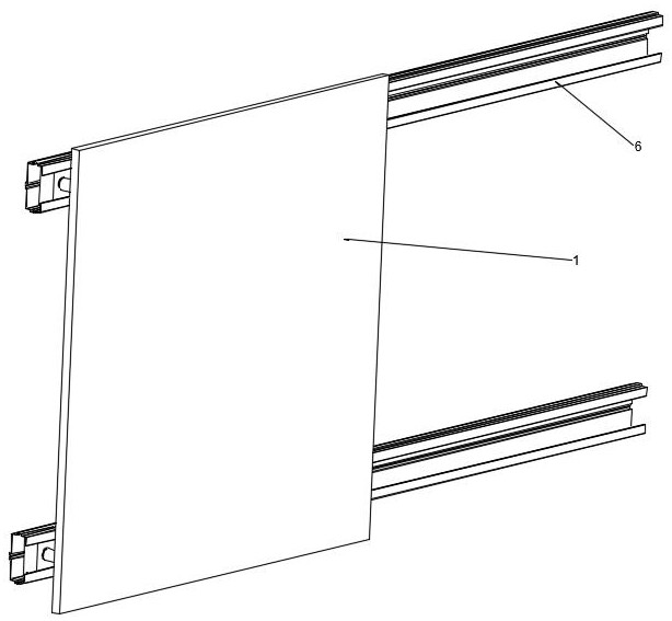
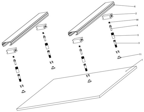
[0050] Such as Figure 1 to Figure 14 As shown, this embodiment provides an assembled wall panel sliding assembly, including: a panel 1 , a movable base 2 , a pressing head 3 , a movable tube 4 , a sleeve 5 and a track keel 6 .

[0051] Four fixing seats 11 are installed on the panel 1 in this embodiment, and the fixing seats 11 are respectively fixed to the four corners of the panel 1 by screws or bolts. The fixing seats 11 are used to connect with the pressing head 3. When pressing the panel 1, the four The fixed seat 11 at the first position is linked with the movement of the pressing head 3 at the same time.

[0052] One end of the pressing head 3 in the present embodiment is provided with eight first wedge-shaped posts 31, and the eight first wedge-shaped posts 31 are evenly arranged along the circumferential direction of the pressing head 3, and the other end of the pressing head 3 is provided with threads, and the threads and the fixing Seat 11 is fixedly connected. O...

Embodiment 2

[0073] This embodiment provides an assembled wall panel sliding assembly, which is different from Embodiment 1 in that:

[0074] In this embodiment, only two fixing seats need to be installed on the panel, and the distance between the two fixing seats corresponds to the distance between two track keels parallel to the original wall; at the same time, the pressing head, movable pipe, sleeve And two movable bases are also installed correspondingly, and after they are assembled, the panel can be moved up or down or slide left and right, saving materials, easy to install and disassemble, and easy to operate.

[0075] For other specific structures, reference may be made to Example 1.


PUM


Abstract

The invention belongs to the technical field of building decoration, and particularly relates to a fabricated wall panel sliding assembly. The sliding assembly comprises a panel, a movable base, a connecting piece and a rail keel; the movable base is provided with a wheel and a threaded hole; one end of the connecting piece is fixedly connected with the threaded hole, and the other end of the connecting piece is fixedly connected with the panel; the rail keel is provided with a sliding rail groove and a wheel groove, and the wheel groove is in rolling fit with the wheel; and the panel is driven to move, so that the connecting piece slides along the sliding rail groove and is linked with the wheel to roll along the wheel groove, and translation of the panel is achieved. The connecting pieceis fixedly connected with the movable base and the panel, rolling can be achieved between the movable base and the rail keel through the wheel, so that left-right translation of the panel is achieved, the opening mode of the panel is a pressing sliding mode, an equipment belt can be hidden in the panel, and interior wall decoration is more attractive.

Description

technical field [0001] The invention belongs to the technical field of architectural decoration, and in particular relates to an assembled wall panel sliding assembly. Background technique [0002] Medical equipment belts are generally installed on the bedside wall in the hospital ward, providing patients with various service facilities such as gas terminals, intercom call systems, data interfaces, lighting or air-conditioning switches, power switches, and bedside lamps. , which is an essential gas terminal control component for central oxygen supply and central suction systems. The existing medical equipment belt installed on the bedside wall of the hospital bed has caused great inconvenience to both the medical staff and the patients. When the connector is inserted, it will disturb or hit the patient, or the patient will block the connector on the equipment belt or accidentally get an electric shock, which will cause life-threatening; and if such an exposed equipment belt...

Claims


Application Information

Patent Timeline
IPC IPC(8): E04F13/074E04F13/22E04F13/23
CPCE04F13/0803E04F13/081E04F2290/02
Inventor 丁欣欣丁泽成王文广周东珊操婷武鹏李鹏程
Owner ZHEJIANG YASHA DECORATION
Learn More