Novel automobile oil filler lock device

A fuel filler and lock device technology, which is applied in the field of new automotive fuel filler lock devices, can solve the problems of simple opening mechanism, simple design of lock tongue mechanism, lack of locking mechanism restrictions on the opening mechanism, etc.

Active Publication Date: 2021-03-05
江苏金鼎汽车锁制造有限公司
View PDF5 Cites 0 Cited by
  • Summary
  • Abstract
  • Description
  • Claims
  • Application Information

AI Technical Summary

Problems solved by technology

[0004] The main purpose of the present invention is to provide a new type of automobile fuel filler lock device, which can effectively solve the problems in the background technology that the opening mechanism is too simple, the opening mechanism lacks necessary locking mechanism restrictions, and the design of the lock tongue mechanism is simple.

Method used


Image

  • Novel automobile oil filler lock device
  • Novel automobile oil filler lock device
  • Novel automobile oil filler lock device

Examples


Embodiment 1

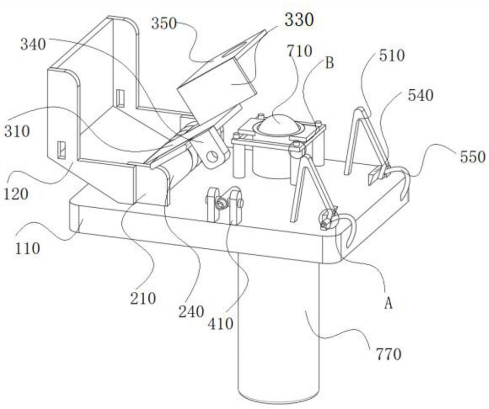
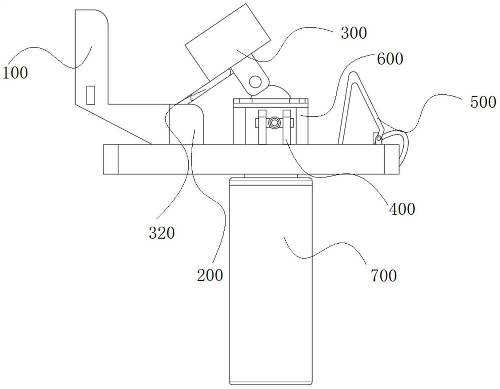
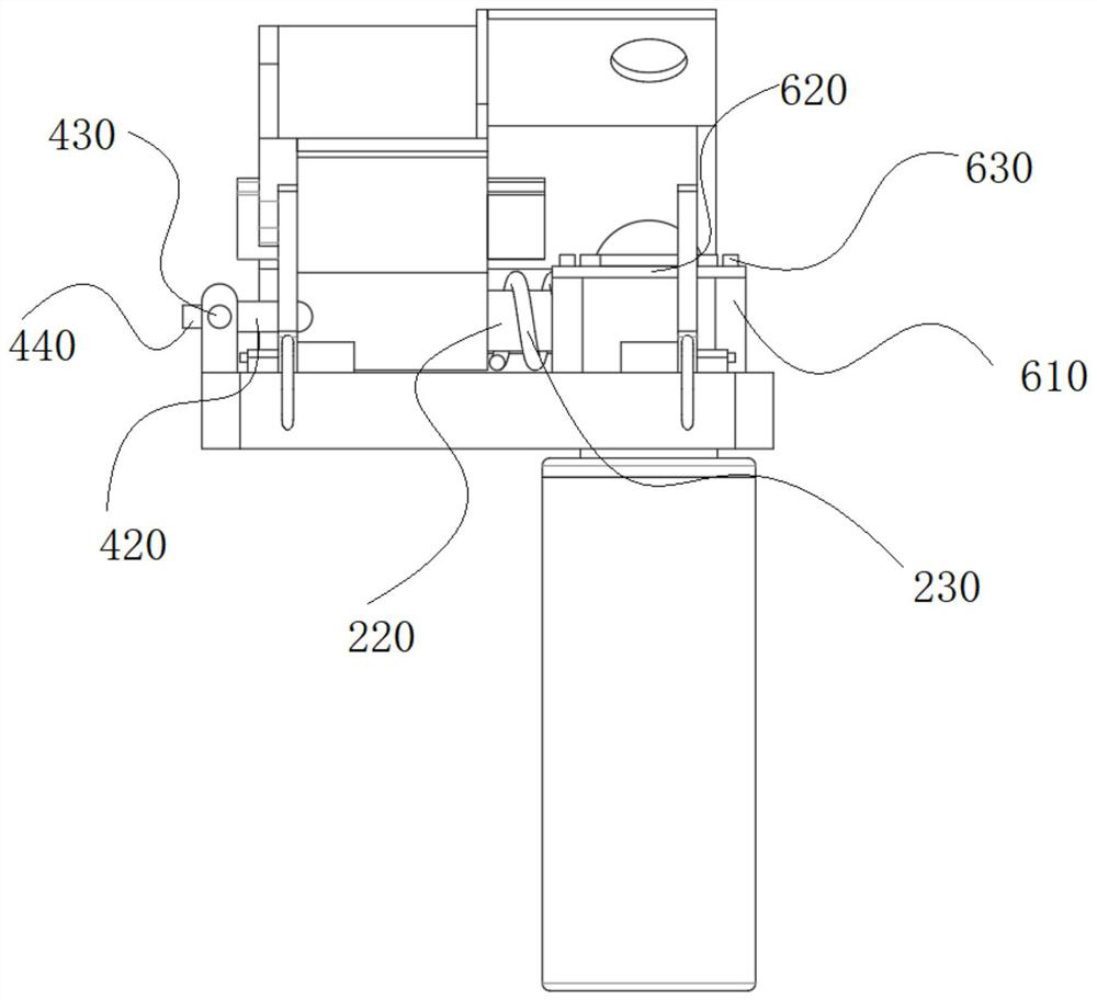
[0034] refer to figure 1—9. The present invention is a new type of automobile refueling port lock device, which includes a base 100, a rebound mechanism 200, an opening mechanism 300, a locking mechanism 400, a connecting mechanism 500, a fixing mechanism 600 and a deadbolt 700. The base 100 includes a bottom plate 110 The rebound mechanism 200 includes a connecting plate 210 and a rotating ring 240, the lower surfaces of the two connecting plates 210 are connected to the upper surface of the bottom plate 110, the opening mechanism 300 includes an opening rocker plate 310, and the first surface of the opening rocker plate 310 is connected to the rotating ring 240 The locking mechanism 400 includes a mounting bracket 410 and a first rotating column 430. One end of the two mounting brackets 410 is connected to the upper surface of the bottom plate 110, and the other ends of the two mounting brackets 410 are respectively connected to the two first rotation columns. The column 430...

Embodiment 2

[0043] The working principle of the present invention is as follows: the clamping plate 320 acts as a limit between the opening rocker plate 310 and the connecting plate 210, the rotating ring 240 rotates, and the perforated cover plate 350 is connected with the limiting column 630 along with the rotating ring 240, To achieve the function of locking and pressing the long column 710, after the connection between the locking plate 340 and the locking column 420 is completed, the position of the opening mechanism 300 is locked, and the movable cover 120 covers the perforated cover 350 in the open state. As a position limiter, the locking plate 340 rotates with the rotating ring 240 to a designated position and connects with the locking column 420, and the lock head 440 is connected with the external structure to complete the locking of the locking angle of the locking column 420, thereby completing the locking of the opening mechanism 300. The position is locked to ensure the lock...


PUM


Abstract

The invention relates to the technical field of automobile parts, in particular to a novel automobile oil filler lock device. The device comprises a base, a springback mechanism, an opening mechanism,a locking mechanism, a connecting mechanism, a fixing mechanism and a spring bolt. The base comprises a bottom plate. The springback mechanism comprises connecting plates and a rotating ring, and thelower surfaces of the two connecting plates are connected with the upper surface of the bottom plate. The opening mechanism comprises an opening rocker arm plate. The locking mechanism comprises mounting clamping seats and first rotating columns. The connecting mechanism comprises connecting frames, connecting clamping seats, second rotating columns and elastic ropes. The fixing mechanism comprises supporting columns and a fixed ring, the lower surfaces of the four supporting columns are connected with the upper surface of the bottom plate, and the lower surface of the fixed ring is connectedwith the upper surface of the bottom plate. The spring bolt comprises a long pressing column and an inner clamping column, and the upper surface of the inner clamping column is connected with the lower surface of the bottom plate. In the device, a positioning column slides in the inner clamping column, the task of compressing a compression spring is completed, namely, the locking state and the opening state are changed, and a clamping block can prevent an outer clamping column and the inner clamping column from sliding and falling off.

Description

technical field [0001] The invention relates to the technical field of automobile parts, in particular to a novel automobile fuel filler lock device. Background technique [0002] The traditional car fuel filler lock is generally installed next to the fuel filler on the outside of the car. When refueling, the driver needs to get out of the car and use the key to unlock it. It is inconvenient to operate, and at the same time increases the structural complexity of the fuel filler, which leads to high product prices and cannot satisfy The driver is convenient to operate and the production and procurement needs of the automobile factory. Therefore, in view of the above problems, the product is improved on the original basis, and the automobile fuel filler lock is installed in the cab, which can make the structure of the entire external fuel filler lock system simple, more convenient and durable. At the same time, it is convenient for the driver to use the opening mechanism to op...

Claims


Application Information

Patent Timeline
Patent Type & Authority Applications(China)
IPC IPC(8): E05B83/34E05B85/00E05B79/10
CPCE05B79/10E05B83/34E05B85/00
Inventor 张国网陆昌盛汪勤民
Owner 江苏金鼎汽车锁制造有限公司
Why Eureka
Try Eureka