Image stitching test method, device and equipment and storage medium

An image stitching and testing method technology, applied in image communication, television, electrical components, etc., can solve the problems of high consumption of manpower and material resources, single scene, inability to judge the adaptability of equipment scene, etc., to improve test accuracy and reduce test manpower. Effect

Active Publication Date: 2021-03-05
ZHEJIANG UNIVIEW TECH CO LTD
View PDF11 Cites 0 Cited by
  • Summary
  • Abstract
  • Description
  • Claims
  • Application Information

AI Technical Summary

Problems solved by technology

[0003] Embodiments of the present invention provide an image splicing test method, device, equipment, and storage medium to solve the technical problems of single scene, large consumption of manpower and material resources, and inability to judge whether the equipment has scene adaptability in the prior art through real scene testing.

Method used


Image

  • Image stitching test method, device and equipment and storage medium
  • Image stitching test method, device and equipment and storage medium
  • Image stitching test method, device and equipment and storage medium

Examples


Embodiment 1

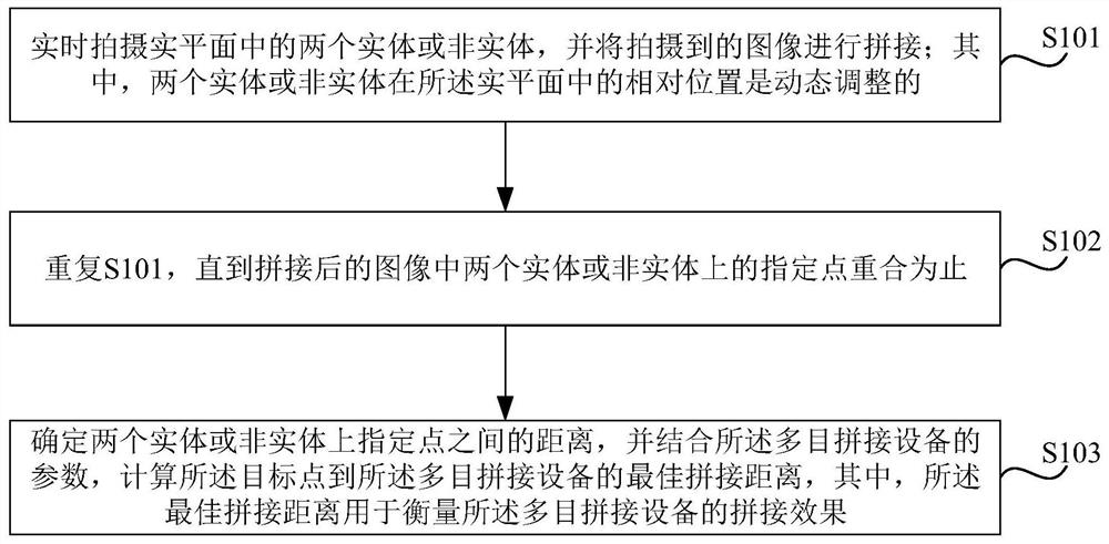
[0029] Figure 1a The flow chart of the image splicing test method provided in Embodiment 1 of the present invention, this embodiment is applicable to the situation where a splicing test is required, the method can be executed by an image splicing test device, and the device can use software and / or hardware way, and can be integrated on equipment, such as integrated on multi-purpose splicing equipment.

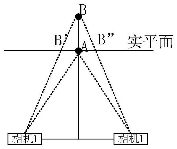
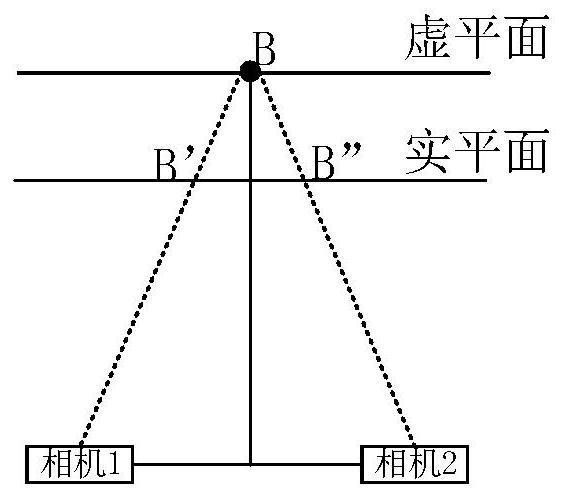
[0030] see Figure 1b , point A is a point that is perfectly spliced ​​into a spliced ​​image, and point B is a point that is spliced ​​abnormally. Then the distance from point A to the camera is the optimal stitching distance of point A. Therefore, if the best splicing positions of all points on the splicing seam are deduced, the splicing effect of the equipment can be measured. from Figure 1b It can be inferred that point B and the real plane intersect at two points B' and B". In the view of the stitching camera, B' and B" can completely replace point B, which is the equ...

Embodiment 2

[0044] Figure 2a The flow chart of the image splicing test method provided by the second embodiment of the present invention, the second embodiment is further optimized on the basis of the first embodiment, and the evaluation of judging the adaptability of the multi-purpose splicing device to the scene is added. Such as Figure 2a As shown, the method includes:

[0045] S201. For any actual scene, calculate a standard splicing distance of the multi-purpose splicing device in the actual scene according to installation parameters corresponding to the multi-purpose splicing device.

[0046] In the embodiment of the present invention, each actual scene corresponds to a mathematical model for calculating the optimal splicing distance. Exemplary, see Figure 2b , taking an open and unobstructed splicing scene as an example, the mathematical model for calculating the optimal splicing distance K in this scene is a function of the viewing angle equalization coefficient n, specifica...

Embodiment 3

[0056] image 3 It is a schematic structural diagram of an image splicing test device in Embodiment 3 of the present invention. The device is configured in a multi-purpose splicing device, and the multi-purpose splicing device includes at least two cameras. Such as image 3 As shown, the device includes:

[0057] Shooting and splicing module 301, used for real-time shooting of two entities or non-entities in the real plane, and splicing the captured images; wherein, the relative positions of the two entities or non-entities in the real plane are dynamically adjusted ;

[0058] The judging module 302 is configured to repeatedly perform the above operations until the specified points on the two entities or non-entities in the spliced ​​image coincide; wherein, when the specified points on the two entities or non-entities coincide, the two The specified point on the entity or non-entity is the two equivalent points of the target point on the image patchwork;

[0059] The firs...


PUM


Abstract

The embodiment of the invention discloses an image stitching test method and device, equipment and a storage medium. The method comprises the steps: shooting two entities or non-entities in a solid plane in real time, splicing the shot images, repeatedly executing the above operations until the specified points on the two entities or non-entities in the spliced image are superposed, wherein when the designated points on the two entities or non-entities coincide, the designated points on the two entities or non-entities are two equivalent points of a target point on the image splicing seam, determining the distance between the specified points on the two entities or non-entities, and calculating the optimal splicing distance from the target point to the multi-view splicing equipment in combination with the parameters of the multi-view splicing equipment. According to the embodiment of the invention, the test of the optimal splicing distance of the splicing points can be completed by measuring the distances between the equivalent entities or non-entities of the splicing points in the solid plane and integrating the equipment parameters, live-action test is not needed, the test manpower is reduced, and the test precision is improved.

Description

technical field [0001] The embodiments of the present invention relate to the field of monitoring, and in particular to an image splicing test method, device, equipment and storage medium. Background technique [0002] In the monitoring field, in order to make the monitoring screen wider, multiple cameras are usually used for image collection, and the collected images are spliced ​​into one screen when outputting. Since there are stitching traces in the images stitched by the multi-eye stitching device, it is necessary to measure the stitching effect of the device. At present, the splicing effect of test equipment needs to be installed in the actual scene, so as to verify the effect of splicing equipment in different scenarios, heights and object distances. However, there are certain deficiencies in the way of real-world testing: the scene is single, the consumption of manpower and material resources is large, and it is impossible to judge whether it has scene adaptability....

Claims


Application Information

Patent Timeline
Patent Type & Authority Applications(China)
IPC IPC(8): H04N17/00
CPCH04N17/00
Inventor 潘胜军
Owner ZHEJIANG UNIVIEW TECH CO LTD
Why Eureka
Try Eureka