A rotary workbench for dismantling waste household appliances

A rotary and workbench technology, applied to workbenches, manufacturing tools, solid waste removal, etc., can solve problems such as inconvenient operation

Active Publication Date: 2022-04-05
赣州市永鑫环保科技有限公司
View PDF11 Cites 0 Cited by
  • Summary
  • Abstract
  • Description
  • Claims
  • Application Information

AI Technical Summary

Problems solved by technology

[0005] In order to overcome the disadvantages of the above-mentioned patents that the waste household appliances cannot be rotated, so that manual adjustment of the angle is required during disassembly, and the operation is relatively inconvenient, the technical problem to be solved by the present invention is to provide a device that can rotate the waste household appliances during disassembly. , which makes manual disassembly more convenient for dismantling waste household appliances with a rotary workbench

Method used


Image

  • A rotary workbench for dismantling waste household appliances
  • A rotary workbench for dismantling waste household appliances
  • A rotary workbench for dismantling waste household appliances

Examples


Embodiment 1

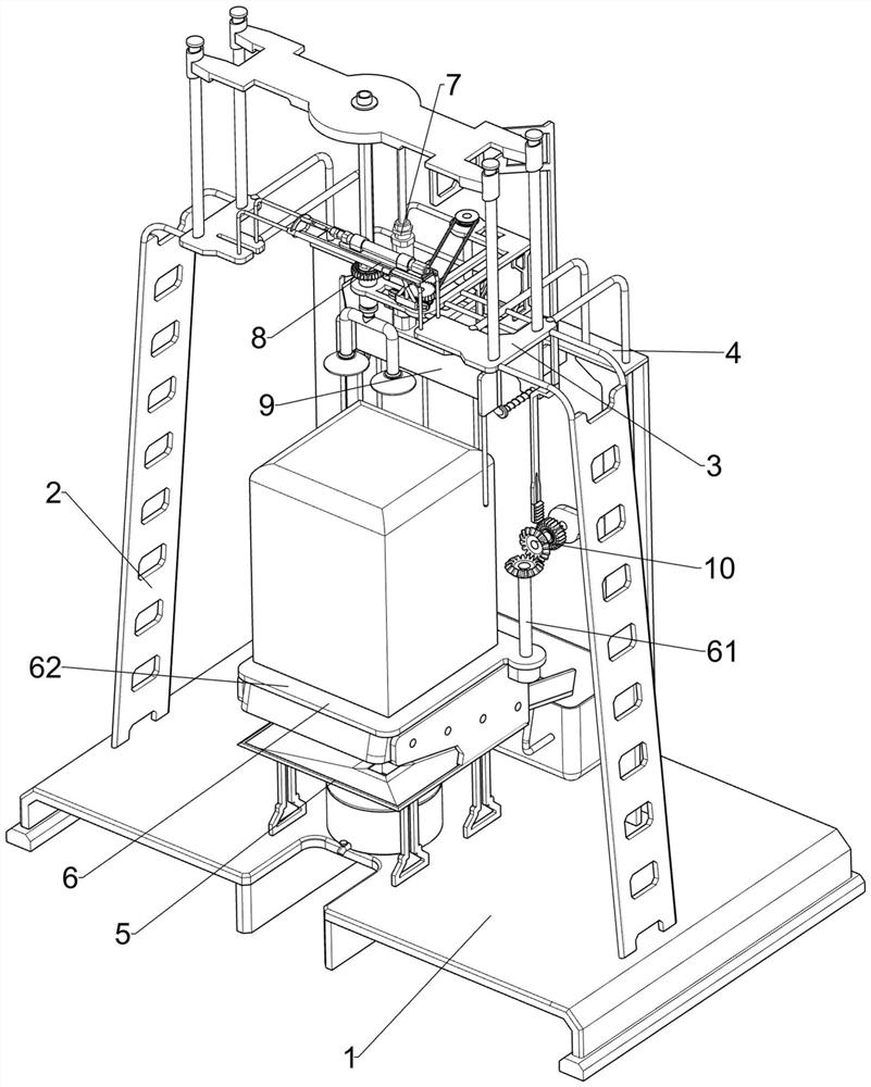
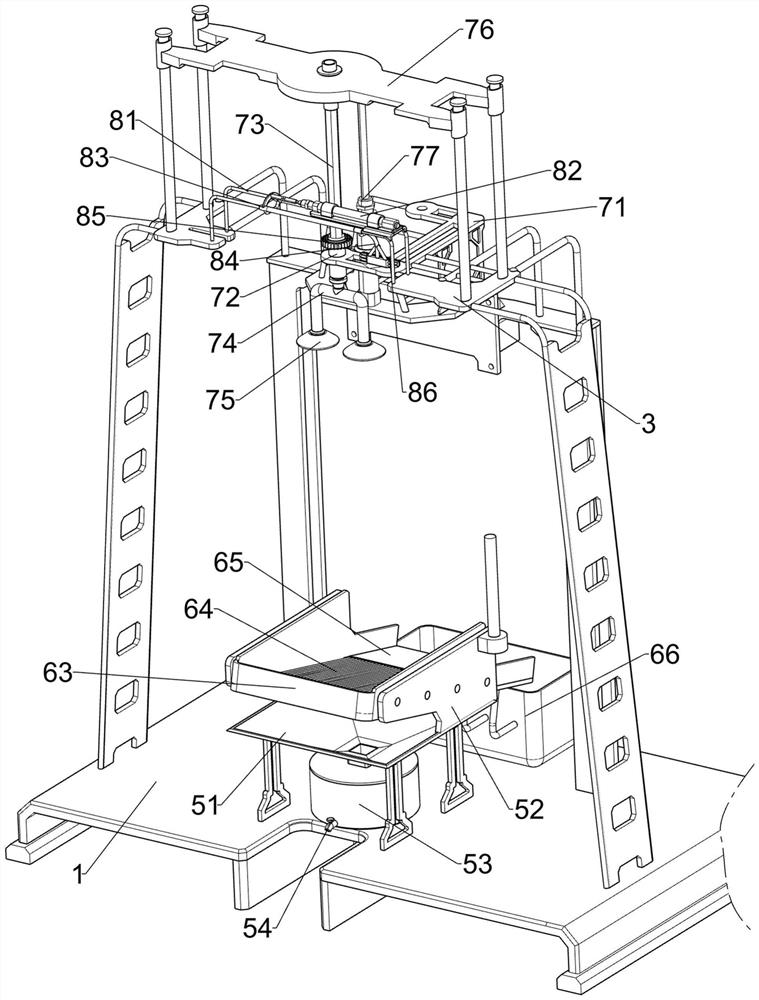
[0025] A rotary workbench for dismantling waste household appliances, such as Figure 1-2 As shown, it includes a base 1, a first bracket 2, a fixed plate 3 and a second bracket 4, the left and right sides of the top of the base 1 are connected with the first bracket 2, the first bracket 2 is connected with a fixed plate 3, the base A second bracket 4 is connected to the top rear side of the seat 1, and the second bracket 4 is connected to the fixed plate 3, and also includes a collection assembly 5, a screening assembly 6, a lifting assembly 7 and a rotating assembly 8, and the base 1 is provided with a collection assembly 5 A screening assembly 6 is provided between the base 1 and the collection assembly 5 , a lifting assembly 7 is provided between the second support 4 and the fixed plate 3 , and a rotating assembly 8 is provided between the lifting assembly 7 and the fixed plate 3 .

[0026] The collection assembly 5 includes a square funnel 51, a first mounting plate 52, a...

Embodiment 2

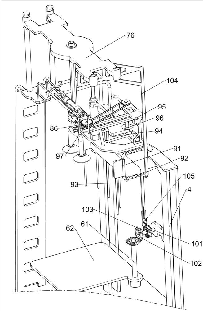
[0033] On the basis of Example 1, such as image 3 As shown, it also includes a limit assembly 9, the limit assembly 9 includes a sliding frame 91, a return spring 92, a limit rod 93, a contact rod 94, a first rotating shaft 95, a cam 96 and a transmission gear 97, on the second support 4 Slidingly connected with sliding frame 91, is connected with return spring 92 between sliding frame 91 and the second support 4, is connected with a plurality of limit rods 93 at the bottom of sliding frame 91, is connected with contact rod 94 at the top of sliding frame 91, and the second installation The plate 71 is rotatably connected with a first rotating shaft 95, the bottom of the first rotating shaft 95 is connected with a cam 96, the cam 96 cooperates with the contact rod 94, and the second mounting plate 71 is rotatably connected with a transmission gear 97, and the transmission shaft of the transmission gear 97 It is transmission connected with the first rotating shaft 95 , and the ...

Embodiment 3

[0036] On the basis of Example 2, such as image 3 As shown, the cover opening assembly 10 is also included. The cover opening assembly 10 includes a second rotating shaft 101, a bevel gear 102, a second one-way gear 103, a second connecting frame 104 and a transmission rack 105, and the middle part of the second bracket 4 rotates. The second rotating shaft 101 is connected with the second rotating shaft 101, the second rotating shaft 101 and the shaft rod 61 are connected with a bevel gear 102, the two bevel gears 102 mesh with each other, the second rotating shaft 101 is connected with a second one-way gear 103, and the slide plate 76 is connected with There is a second connecting frame 104 , and a transmission rack 105 is connected to the second connecting frame 104 , and the transmission rack 105 will mesh with the second one-way gear 103 .

[0037] When the slide plate 76 moves up and down, the second connecting frame 104 drives the transmission rack 105 to move up and do...


PUM


Abstract

The invention relates to a workbench, in particular to a rotary workbench for dismantling waste household appliances. The technical problem to be solved by the present invention is how to design a rotary workbench for dismantling waste and old household appliances that can be rotated during disassembly to make manual disassembly more convenient. In order to solve the above technical problems, the present invention provides such a rotary workbench for dismantling waste household appliances, which includes: a base, a first bracket connected to both sides of the top, and a fixing plate connected to the first bracket; Two brackets, which are connected to one side of the top of the base, and the second bracket is connected to the fixed plate; the collection assembly, which is arranged on the base; the screening assembly, which is arranged between the base and the collection assembly; the lifting assembly, which is arranged on Between the second bracket and the fixed plate; the rotating component is arranged between the lifting component and the fixed plate. The present invention achieves the basic function as a workbench through the cooperative operation of the screening assembly and the lifting assembly.

Description

technical field [0001] The invention relates to a workbench, in particular to a rotary workbench for dismantling waste household appliances. Background technique [0002] Household appliances mainly refer to various electrical appliances and electronic appliances used in homes and similar places. Also known as civil appliances, household appliances. Household appliances liberate people from heavy, trivial and time-consuming housework, create a more comfortable and beautiful living and working environment that is more conducive to physical and mental health, and provide rich and colorful cultural and entertainment conditions. necessities of life. Home appliances will be damaged after being used for a long time. Broken home appliances are also called waste home appliances. Waste home appliances usually need to be sent to recycling bins for disposal. During disposal, waste home appliances usually need to be disassembled. [0003] After retrieval, the patent publication numbe...

Claims


Application Information

Patent Timeline
Patent Type & Authority Patents(China)
IPC IPC(8): B25H1/06B25H1/10B25H1/12B25H1/16B25H1/18B09B3/30B09B101/15
CPCB25H1/06B25H1/10B25H1/12B25H1/16B25H1/18B09B3/00
Inventor 焦培连
Owner 赣州市永鑫环保科技有限公司
Why Eureka
Try Eureka