Transfer case, chassis assembly and crane
A transfer case and crane technology, applied in auxiliary drive devices, control devices, transportation and packaging, etc., can solve problems such as errors in neutral feedback signals, and achieve the effects of avoiding failures and improving safety performance
- Summary
- Abstract
- Description
- Claims
- Application Information
AI Technical Summary
Problems solved by technology
Method used
Image

Examples
Embodiment 1
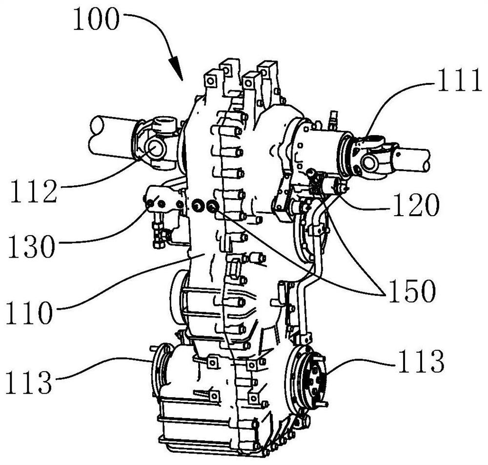
[0047] see figure 1 , a transfer case 100 provided in this embodiment is applied to the chassis assembly of a crane, and is used to selectively transmit the power of the engine 200 in the chassis assembly to the lifting chassis to perform driving operations or top loading to perform hoisting operations .
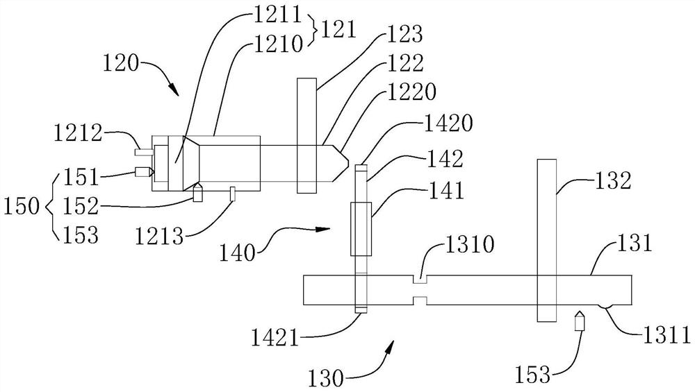
[0048] Please refer to figure 1 and figure 2 , the transfer case 100 provided in this embodiment includes a transfer case body 110, a first power take-off mechanism 120, a second power take-off mechanism 130 and an interlock mechanism 140, wherein the first power take-off mechanism 120, the second power take-off mechanism 130 and the interlock mechanism 140 are both arranged on the transfer case body 110 .
[0049] The transfer case body 110 is a shell structure, and the transfer case body 110 includes an input end 112 , a bodywork output end 111 and a chassis output end 113 .
[0050] The first power take-off mechanism 120 is used to connect the bodywork output end 111...
Embodiment 2
[0082] see figure 1 , a transfer case 100 provided in this embodiment is applied to the chassis assembly of a crane, and is used to selectively transmit the power of the engine 200 in the chassis assembly to the lifting chassis to perform driving operations or top loading to perform hoisting operations . This embodiment is an improvement made on the basis of the above-mentioned embodiment 1. Compared with the above-mentioned embodiment 1, the main difference is:
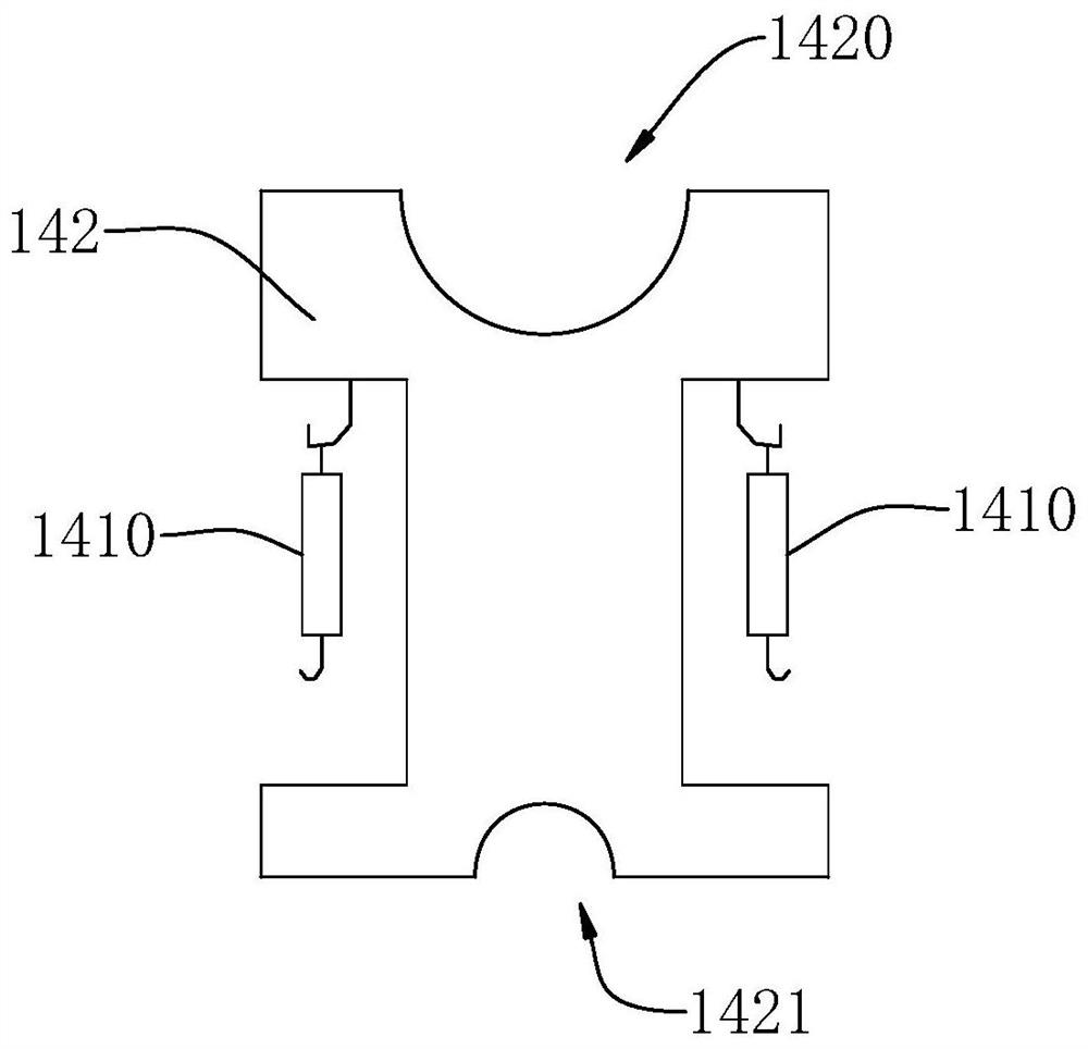
[0083] Please refer to figure 2 and image 3 , in this embodiment, the interlocking piece 142 is a sheet structure, and the sliding direction of the interlocking piece 142 is perpendicular to the first power take-off axis 122 and the second power take-off axis 131 . The first interlocking end 1420 and the second interlocking end 1421 are respectively disposed at ends of the interlocking member 142 along the length direction of the interlocking member 142 .
[0084] The end of the first power take-off shaft 122 i...
Embodiment 3
[0095] see figure 1 and figure 2 , a transfer case 100 provided in this embodiment is applied to the chassis assembly of a crane, and is used to selectively transmit the power of the engine 200 in the chassis assembly to the lifting chassis to perform driving operations or top loading to perform hoisting operations . This embodiment is an improvement made on the basis of the above-mentioned embodiment 1 or embodiment 2. Compared with the above-mentioned embodiment 1 or embodiment 2, the main difference is:
[0096] In some specific embodiments, both the first power take-off mechanism 120 and the second power take-off mechanism 130 include a predetermined number of position sensors 150, and the predetermined number of position sensors are used to detect the corresponding first power take-off shaft 122 and the second power take-off shaft 150 respectively. The power take-off state of the two power take-off shafts 131.
[0097] Further, a predetermined number of position senso...
PUM
 Abstract
Description
Claims
Application Information
 - R&D
- Intellectual Property
- Life Sciences
- Materials
- Tech Scout
- Unparalleled Data Quality
- Higher Quality Content
- 60% Fewer Hallucinations
Browse by: Latest US Patents, China's latest patents, Technical Efficacy Thesaurus, Application Domain, Technology Topic, Popular Technical Reports.
© 2025 PatSnap. All rights reserved.Legal|Privacy policy|Modern Slavery Act Transparency Statement|Sitemap|About US| Contact US: help@patsnap.com