A detection device and detection method for automatic bagging weighing
A detection device and bagging technology, applied in the directions of packaging automatic control, packaging, packaging protection, etc., can solve the problems of inconvenient bagging and weighing, low overall efficiency, etc., to improve production efficiency and detection accuracy, and reduce the occupation of Space, the effect of reducing the number of starts and stops and the probability of backflow
- Summary
- Abstract
- Description
- Claims
- Application Information
AI Technical Summary
Problems solved by technology
Method used
Image
Examples
Embodiment 1
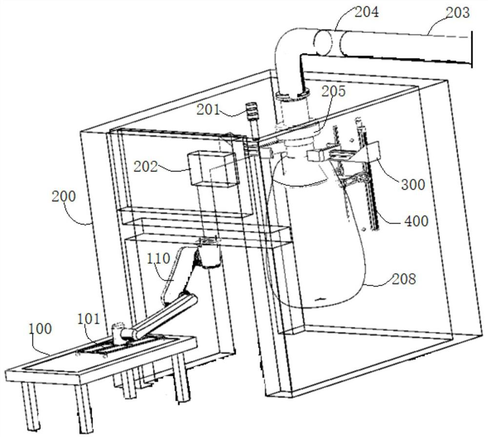
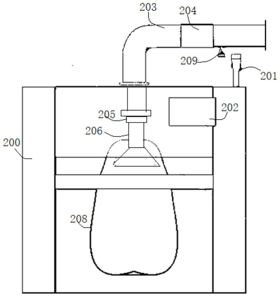
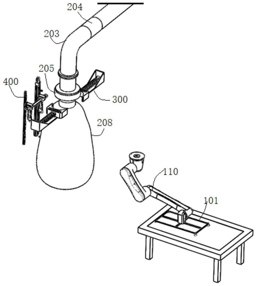
[0046] like Figure 1-Figure 10 As shown, an automatic bagging weighing detection device in this embodiment includes a working frame 200, a feeding pipe 203 is arranged on the working frame 200, and a load cell 205 is installed at the discharge position of the feeding pipe 203; The frame 200 is also provided with a bag holding mechanism 400 and a bag tightening mechanism 300. The bag tightening mechanism 300 is arranged on both sides of the discharge port 207 of the feeding pipe 203, and each side includes a jaw 303 and a mechanism for driving the jaw 303 to expand and contract. Pushing power member; the bag opening mechanism 400 includes a first suction cup 407 and a second suction cup 411 for sucking the accommodating bag 208. The first suction cup 407 and the second suction cup 411 are connected to the lifting power member, and are driven to rise and fall by it.
[0047] Specifically, in this embodiment, a spoke-type load cell 205 is installed on the feeding pipe 203, and a...
Embodiment 2
[0052] A detection device for automatic bagging and weighing in this embodiment is basically the same as that in Embodiment 1, and further, such as Figure 9 As shown, in this embodiment, the bag-supporting mechanism 400 includes an active guide rail frame 401 and an auxiliary guide rail 402 that are arranged in parallel in the work frame 200 . The active arm 406 extending outward, the outer end of the active arm 406 is provided with a first suction cup 407; the auxiliary guide rail 402 is correspondingly provided with an auxiliary fixing seat 409, and the auxiliary fixing seat 409 is provided with an outwardly extending follower arm 410, from The outer end of the boom 410 is provided with a second suction cup 411 ; the driving arm 406 and the driven arm 410 are connected by a connecting shaft 408 , and the driving rail frame 401 is provided with a power member for driving the main fixing base 404 to rise and fall.
[0053] Specifically, the power member is a first power motor...
Embodiment 3
[0055] The detection device for automatic bagging and weighing in this embodiment is basically the same as the above-mentioned embodiment. Furthermore, in this embodiment, the active arm 406 can be rotated and fitted on the main fixing seat 404 through the bearing, and the driven arm 410 is also It is rotatably mounted on the sub-fixed seat 409, and one end of the active arm 406 is provided with a rotational power for driving it to turn over. Specifically, the end of the active arm 406 is provided with a second power motor 405, the output shaft end of the second power motor 405 is connected to the connecting shaft 408, and the second power motor 405 drives the connecting shaft 408 to rotate, that is, drives the active arm 406 and the slave The boom 410 flips over. The active arm 406 and the driven arm 410 can be turned from the original outwardly extending state to the attached state parallel to the active guide rail frame 401 and the auxiliary guide rail 402, thereby effectiv...
PUM
 Abstract
Description
Claims
Application Information
 - R&D
- Intellectual Property
- Life Sciences
- Materials
- Tech Scout
- Unparalleled Data Quality
- Higher Quality Content
- 60% Fewer Hallucinations
Browse by: Latest US Patents, China's latest patents, Technical Efficacy Thesaurus, Application Domain, Technology Topic, Popular Technical Reports.
© 2025 PatSnap. All rights reserved.Legal|Privacy policy|Modern Slavery Act Transparency Statement|Sitemap|About US| Contact US: help@patsnap.com


