Al technical title is built by PatSnap Al team. It summarizes the technical point description of the patent document.
A vacuuming device and operation technology, applied in the directions of loading/unloading, transportation and packaging, conveyors, etc., can solve the problem of incomplete dust removal effect, and achieve easy centralized maintenance and treatment, sufficient dust removal effect, and avoid occupying too much space. Effect
Inactive Publication Date: 2021-03-09
安徽华晟环保设备科技有限公司
View PDF11 Cites 1 Cited by
Summary
Abstract
Description
Claims
Application Information
AI Technical Summary
This helps you quickly interpret patents by identifying the three key elements:
Problems solved by technology
Method used
Benefits of technology
Problems solved by technology
[0003] The invention patent with the patent number of CN103302073A discloses a suction and dust removal device for a grain pit, which includes a dust collector, a feeding port and a conveying device. There is an air suction port on the side wall, and the air suction port is connected with the dust collector through the air pipe; the conveying device is arranged under the grain pit, and the present invention can ensure that less dust can fly upwards and be absorbed by the human body, while ensuring the lower The material is unobstructed and has a good suction and dust removal effect, and the working area of the feeding port is large, which improves the work efficiency and reduces the work intensity. However, this device only achieves the effect of dust collection through the connection of the ventilation device and the dust collection device, but it does not make the grain The existing dust is removed, and the dust removal effect is not complete
Method used
Image
Click on the blue label to locate the original text in one second.
Reading with bidirectional positioning of images and text.
Examples
Embodiment Construction
[0022] The following will clearly and completely describe the technical solutions in the embodiments of the present invention with reference to the accompanying drawings in the embodiments of the present invention. Obviously, the described embodiments are only some, not all, embodiments of the present invention. Based on the embodiments of the present invention, all other embodiments obtained by persons of ordinary skill in the art without creative efforts fall within the protection scope of the present invention.
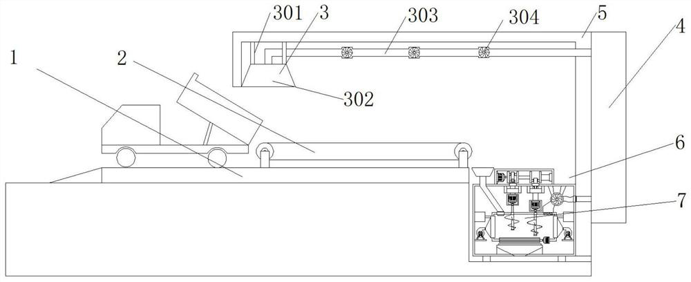
[0023] see Figure 1-3 As shown, a high-efficiency dust collection device for grain unloading operation includes a grain unloading platform 1, a conveyor belt 2, an exhaust system 3, a dust collection box 4, a wall 5, a foundation pit 6, and a dust suction device 7. The wall 5 In a vertical structure, the bottom of one side of the wall 5 is fixedly connected with an exhaust system 3, the bottom of the wall 5 is provided with a grain unloading platform 1, and the to...
PUM
Abstract
An efficient grain unloading operation dust collection device comprises a grain unloading platform, a conveyor belt, an air draft system, a dust collection box, a wall body, a foundation pit and a dust collection device, and is characterized in that the wall body is of a vertical structure, the air draft system is fixedly connected to the bottom of one side of the wall body, the grain unloading platform is arranged below the bottom of the wall body, the conveyor belt is fixedly connected to the top of the grain unloading platform, the foundation pit is formed between the conveyor belt and theother side of the wall body, the dust collection device is fixedly mounted in the foundation pit, the dust collection box is fixedly connected to one side, close to the outer side, of the wall body, and the dust collection device comprises a first motor, a connecting shaft, a crankshaft, a first box body, a shaft sleeve, a support, a rotating wheel, a first air outlet, an air inlet, a filter screen, an air blower, an installation plate, a discharging port, a blocking wheel, a stirring wheel, a first rotating shaft, a motor case, a second motor, a limiting frame, a connecting block and a feeding hopper. Grains are scattered through the stirring wheel, the air blower blows out the dust in the grains, and the dust is sucked into the dust collection box through the rotating wheel.
Description
technical field [0001] The invention relates to the technical field of dust collection devices, in particular to a high-efficiency dust collection device for unloading grain. Background technique [0002] With the continuous development of the industrial level, people's living standards continue to improve, and people's attention to the body is also increasing. In the conventional grain unloading operation, a large amount of dust entrained in the grain will be raised, which is harmful to the environment and the body of the workers. There is a certain degree of damage, so the existing grain processing and feed processing enterprises basically use the upper suction dust removal device at the grain pit. This device sucks the dust into the dust collector through the suction port above the operator's body for dust removal. [0003] The invention patent with the patent number of CN103302073A discloses a suction and dust removal device for a grain pit, which includes a dust collect...
Claims
Application Information
Patent Timeline
Application Date:The date an application was filed.
Publication Date:The date a patent or application was officially published.
First Publication Date:The earliest publication date of a patent with the same application number.
Issue Date:Publication date of the patent grant document.
PCT Entry Date:The Entry date of PCT National Phase.
Estimated Expiry Date:The statutory expiry date of a patent right according to the Patent Law, and it is the longest term of protection that the patent right can achieve without the termination of the patent right due to other reasons(Term extension factor has been taken into account ).
Invalid Date:Actual expiry date is based on effective date or publication date of legal transaction data of invalid patent.