
Converging plate for bottle blowing machine and bottle blowing equipment using converging plate

A manifold and bottle blowing machine technology, applied in the field of bottle blowing molds, can solve the problems of inconvenient installation, maintenance, large air pipe consumption, etc., and achieve the effects of regular structure layout, improved product quality, and improved space utilization

Active Publication Date: 2020-12-18
深圳市得宝来自动化科技有限公司
View PDF10 Cites 0 Cited by
  • Summary
  • Abstract
  • Description
  • Claims
  • Application Information

AI Technical Summary

Problems solved by technology

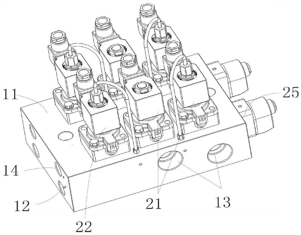
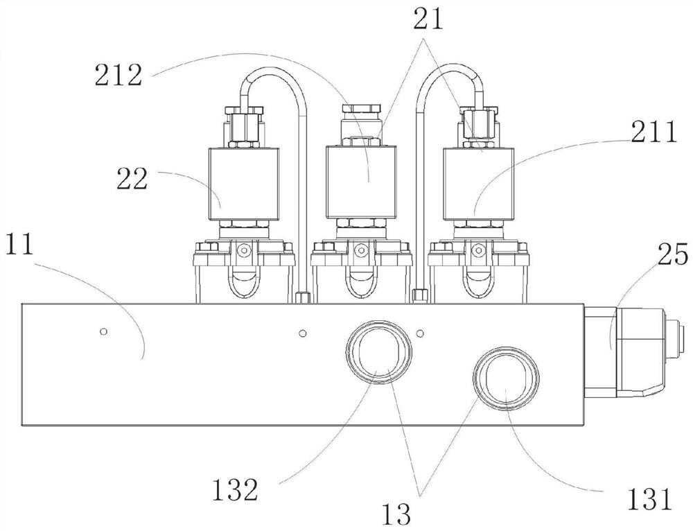
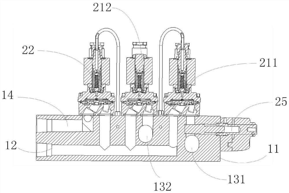
[0004] The invention provides a manifold for bottle blowing machines, through which several solenoid valves for bottle blowing machines are integrated and installed to solve the problem of installing two-position, two-way valves on the surface of the mold cavity in the prior art. The air pipe connecting the blow molding machine and the two-way solenoid valve consumes a large amount, which is inconvenient for installation and maintenance

Method used


Image

  • Converging plate for bottle blowing machine and bottle blowing equipment using converging plate
  • Converging plate for bottle blowing machine and bottle blowing equipment using converging plate
  • Converging plate for bottle blowing machine and bottle blowing equipment using converging plate

Examples


no. 2 example

[0117] combine Figure 5 , Figure 9 and Figure 10 ,in Figure 5 It is a perspective view of the second embodiment of the blow molding machine manifold of the present invention, Figure 9 It is a structural schematic diagram of the second total air delivery channel of the second embodiment of the manifold for bottle blowing machine of the present invention, Figure 10 It is a schematic structural diagram of the second air inlet channel of the second embodiment of the manifold for bottle blowing machine of the present invention. Several electromagnetic valve groups in the present embodiment also comprise the second inlet valve group 43 and the second exhaust valve group, the second inlet valve group 43 is used for controlling the input of the gas in the mold cavity, and the second exhaust valve group is used for To control the output of gas in the mold cavity; the second intake valve group 43 in this embodiment includes at least one second intake valve, and the second exha...

no. 3 example

[0134] Please refer to Figure 12 , Figure 14 and Figure 15 , Figure 12 It is a perspective view of the third embodiment of the blow molding machine manifold of the present invention, Figure 14 It is a side view of the third embodiment of the blow molding machine manifold of the present invention, Figure 15 It is a cross-sectional schematic view of the internal structure of the third embodiment of the manifold for bottle blowing machine of the present invention.

[0135] The following is a blow molding machine manifold that can solve the above technical problems provided by the present invention, which is used to assemble the solenoid valves of the blow molding machine. Several solenoid valve groups include the first inlet valve group 61 and the first exhaust valve Group 62; wherein, the first air intake valve group 61 includes at least one air intake valve, used to control the input of gas in the mold cavity; the first exhaust valve group 62 includes at least one exh...


PUM


Abstract

The invention provides a converging plate for a bottle blowing machine. The converging plate is used for containing electromagnetic valves of the bottle blowing machine, and a plurality of electromagnetic valve groups comprise a first gas inlet valve group and a first exhaust valve group; and the converging plate comprises a converging plate body, and a first main gas transmission channel, a firstgas inlet channel and a first exhaust channel, wherein the first main gas transmission channel, the first gas inlet channel and the first exhaust channel are arranged in the converging plate body. The first main gas transmission channel is connected with a mold cavity, one end of the first gas inlet channel is connected with gas supply equipment, and the other end of the first gas inlet channel is connected with the first main gas transmission channel through the first gas inlet valve group. One end of the first exhaust channel is connected with the first main gas transmission channel throughthe first exhaust valve group, and the other end of the first exhaust channel extends out of the converging plate body. According to the converging plate for the bottle blowing machine, the pluralityof electromagnetic valves for the bottle blowing machine can be integrally installed, a user can conveniently control the electromagnetic valves in a centralized manner, the use quantity of gas pipesused by the bottle blowing machine and the bottle blowing equipment is reduced, the time needed for installing the gas pipes is shortened, the arrangement structure of the electromagnetic valves of the bottle blowing machine is simple, and the electromagnetic valves are convenient to replace.

Description

technical field [0001] The invention relates to the field of bottle blowing molds, in particular to a manifold for a bottle blowing machine. Background technique [0002] The bottle blowing machine is a machine that can blow the finished preforms into bottles through certain technological means. With the rapid development of social science and economy, bottle blowing machines are widely used in beverage, medicine, cosmetics, food and chemical industries. [0003] At present, when the bottle blowing machine performs the blowing operation, the corresponding two-position two-way valve is installed on the surface of the mold cavity, which is not easy to manage; moreover, the air pipe connecting the blow molding machine equipment and the two-way valve consumes a lot, which is not easy to install and maintain , poor practicability, and serious potential safety hazards. Therefore, it is necessary to provide a manifold for bottle blowing machines to solve the above technical probl...

Claims


Application Information

Patent Timeline
IPC IPC(8): B29C49/42
CPCB29C49/42B29C49/4289
Inventor 梁毅
Owner 深圳市得宝来自动化科技有限公司
Learn More