Motor airtightness detection device

A technology for air tightness detection and detection, which is applied in the direction of liquid tightness measurement using liquid/vacuum degree, and by measuring the increase and deceleration rate of the fluid, which can solve the problems of low efficiency and large error rate

Active Publication Date: 2020-04-14
台州孚亚电机有限公司
View PDF8 Cites 0 Cited by
  • Summary
  • Abstract
  • Description
  • Claims
  • Application Information

AI Technical Summary

Problems solved by technology

[0002] As an indispensable and important part of all kinds of electric machinery nowadays, the motor has a huge market demand, and under the huge market demand, the quality of the motor to be tested will naturally increase, and the airtightness of the motor is undoubtedly It is an extremely important part. Existing air tightness detection devices are often tested by gap contact with probes. This method is not only inefficient, but also has a large error rate.

Method used


Image

  • Motor airtightness detection device
  • Motor airtightness detection device
  • Motor airtightness detection device

Examples


Embodiment Construction

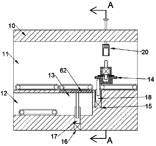
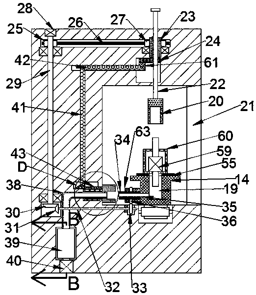
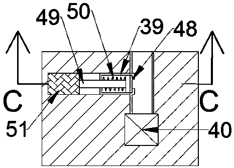
[0017] Combine below Figure 1-5 The present invention is described in detail, and for convenience of description, the orientations mentioned below are now stipulated as follows: figure 1 The up, down, left, right, front and back directions of the projection relationship itself are the same.

[0018] refer to Figure 1-5 According to an embodiment of the present invention, a motor airtightness detection device includes a body 10, and is characterized in that: the body 10 is provided with a left and right through working chamber 11, and the working chamber 11 is horizontally provided with three A conveyor belt mechanism, the motor to be tested is transported into the working chamber 11 through the conveyor belt mechanism in the third section from left to right, and then transported out of the working chamber 11 through the conveyor belt mechanism in the first section from left to right. The chamber to be repaired 12 is provided below the working chamber 11, and the upper righ...


PUM


Abstract

The invention discloses a motor airtightness detection device. The device comprises a body, the device is characterized in that a working cavity which is through left and right is formed in the body;three sections of conveying belt mechanisms are horizontally arranged in the working cavity; a to-be-detected motor is conveyed into the working cavity through the third section of the conveying beltmechanism from left to right; the first section of the conveying belt mechanism is conveyed away from the working cavity from left to right, a to-be-repaired cavity is formed below the working cavity,a descending opening communicating with the working cavity is formed in the upper right portion of the to-be-repaired cavity, a second air cylinder is arranged below the descending opening, and a second air cylinder rod capable of extending up and down is arranged at the upper end of the second air cylinder; according to the device, the lower pressing block moves downwards to enable the motor shell to sink slightly; the sealing ring deforms, meanwhile, the hollow screw rod is rotationally sleeved with the airtight threaded sleeve, so that an airtight environment is constructed, a vacuum environment is constructed for the sealing ring through an air pump, then the sealing ring is static for a moment, and whether the airtightness of the motor to be detected is good is determined by detecting the internal air pressure of the sealing ring.

Description

technical field [0001] The invention relates to the technical field of motors, in particular to a motor air tightness detection device. Background technique [0002] As an indispensable and important part of all kinds of electric machinery nowadays, the motor has a huge market demand, and under the huge market demand, the quality of the motor to be tested will naturally increase, and the airtightness of the motor is undoubtedly It is an extremely important part. Existing air tightness detection devices are often tested by gap contact with probes. This type of method not only has low efficiency, but also has a large error rate. Contents of the invention [0003] The object of the present invention is to provide a motor air tightness detection device for overcoming the above-mentioned defects in the prior art. [0004] A motor airtightness detection device according to the present invention includes a fuselage, and is characterized in that: the fuselage is provided with a l...

Claims


Application Information

Patent Timeline
Patent Type & Authority Applications(China)
IPC IPC(8): G01M3/26
CPCG01M3/26
Inventor 不公告发明人
Owner 台州孚亚电机有限公司
Why Eureka
Try Eureka