Automatic hoisting feeding and discharging device for mechanical equipment manufacturing workshop

A technology for manufacturing workshops and mechanical equipment, which is applied in the field of automatic hoisting and loading and unloading devices for mechanical equipment manufacturing workshops. It can solve the problems of heavy physical exertion of workers, poor safety and practicability, and low work efficiency, so as to improve practicability and reliability. , to facilitate heat dissipation and improve practicality

Inactive Publication Date: 2021-03-09
苏州立科工业设计有限公司
View PDF0 Cites 0 Cited by
  • Summary
  • Abstract
  • Description
  • Claims
  • Application Information

AI Technical Summary

Problems solved by technology

[0002] As we all know, when the workshop machinery and equipment process the workpiece, it usually requires multiple sets of equipment to work together to increase the processing speed of the workpiece. When the workpiece is processed, it is necessary to manually disassemble the preliminary processed workpiece from the equipment, and then transfer and install it. On the next set of equipment, the processing of the workpiece can be realized. However, when this method is adopted, the way of manually loading and unloading and transferring the workpiece between the equipment is relatively cumbersome, and the physical exertion of the workers is large, and the work efficiency is low. Simultaneously running Equipment is prone to injury to workers, resulting in poor safety and usability

Method used


Image

  • Automatic hoisting feeding and discharging device for mechanical equipment manufacturing workshop
  • Automatic hoisting feeding and discharging device for mechanical equipment manufacturing workshop
  • Automatic hoisting feeding and discharging device for mechanical equipment manufacturing workshop

Examples


Embodiment Construction

[0020] The specific implementation manners of the present invention will be further described in detail below in conjunction with the accompanying drawings and embodiments. The following examples are used to illustrate the present invention, but are not intended to limit the scope of the present invention.

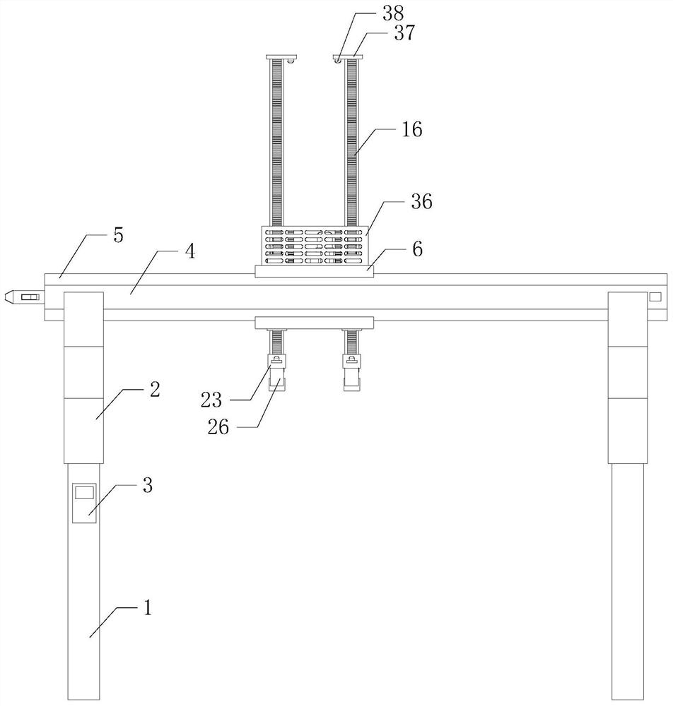
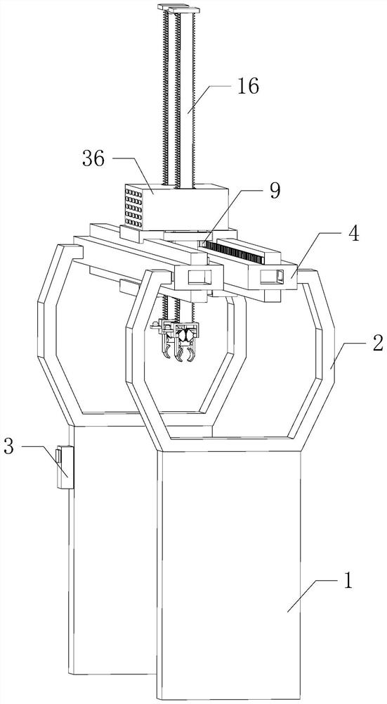
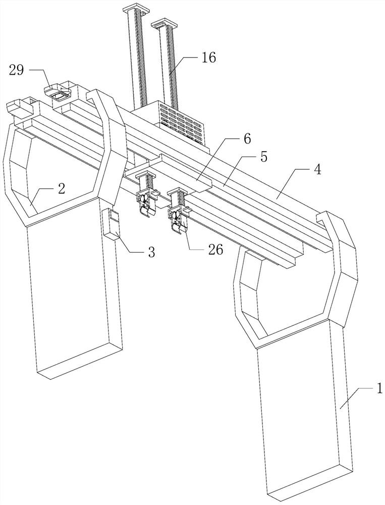
[0021] Such as Figure 1 to Figure 6 As shown, the automatic lifting and loading and unloading device for the mechanical equipment manufacturing workshop of the present invention, when it is working, the central control box 3 controls to open the first motor 12, and the first motor 12 drives the double output shaft reducer 11 to run, and the double output shaft decelerates The device 11 respectively drives two groups of worm gears 10 to rotate through two groups of worms 13, and the rotation directions of the two groups of worm gears 10 are opposite. Mesh with the teeth on the two sets of guide rails 5 on the upper side respectively, the two sets of first gears 9 roll on ...


PUM


Abstract

The invention relates to the technical field of mechanical equipment, in particular to an automatic hoisting feeding and discharging device for a mechanical equipment manufacturing workshop. Accordingto the automatic hoisting feeding and discharging device, automatic feeding and discharging work is conducted on mechanical equipment in the workshop, multiple sets of equipment in the workshop can conveniently work cooperatively, manpower and time for manual feeding and discharging and workpiece transferring are saved, the workpiece machining manner is simplified, and the work efficiency is improved; and meanwhile, the equipment in the running state is prevented from hurting workers, and practicability and safety are improved. The automatic hoisting feeding and discharging device comprises two sets of supporting legs, two sets of U-shaped frames, a center control box and two sets of long fixing plates. The bottoms of the two sets of U-shaped frames are arranged on the two sets of supporting legs correspondingly. The center control box is arranged on the front side of the supporting leg on the left side. The two sets of long fixing plates are located on the upper sides of the two setsof U-shaped frames. The left sides and the right sides of the outer side walls of the two sets of long fixing plates are arranged on the front sides and the rear sides of the tops of the two sets ofU-shaped frames correspondingly.

Description

technical field [0001] The invention relates to the technical field of mechanical equipment, in particular to an automatic hoisting and unloading device for a mechanical equipment manufacturing workshop. Background technique [0002] As we all know, when the workshop machinery and equipment process the workpiece, it usually requires multiple sets of equipment to work together to increase the processing speed of the workpiece. When the workpiece is processed, it is necessary to manually disassemble the preliminary processed workpiece from the equipment, and then transfer and install it. On the next set of equipment, the processing of workpieces can be realized. However, when this method is adopted, the way of manual loading and unloading and transferring workpieces between equipments is relatively cumbersome, and the physical exertion of workers is large, and the work efficiency is low. Simultaneously running Equipment is prone to injury to workers, resulting in poor safety a...

Claims


Application Information

Patent Timeline
Patent Type & Authority Applications(China)
IPC IPC(8): B66C1/44B66C13/04B66C13/18B23Q7/00B23Q7/04
CPCB23Q7/005B23Q7/04B66C1/44B66C13/04B66C13/18
Inventor 高洪庆吴禹凡
Owner 苏州立科工业设计有限公司
Why Eureka
Try Eureka