
Biogas digester safety pressure relief device

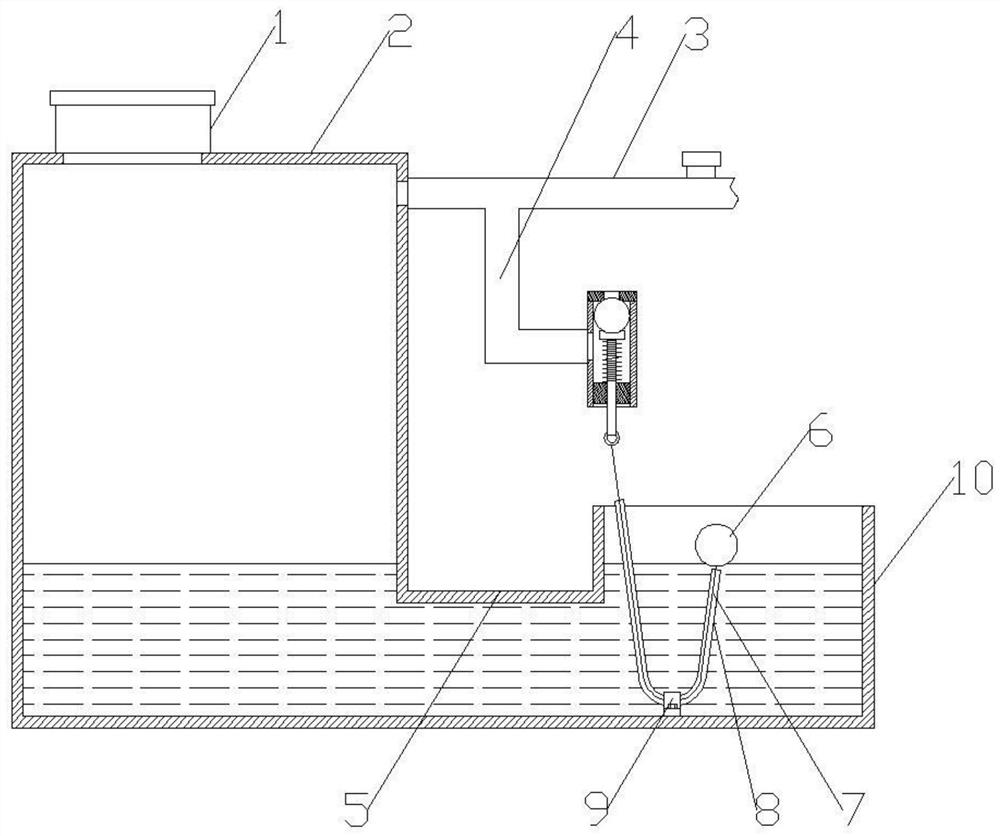
A technology of pressure relief device and biogas digester, which is applied in the direction of biochemical cleaning device, enzymology/microbiology device, gas production bioreactor, etc., which can solve the problem of increased air pressure in the main tank, which is easy to cause danger, and the addition of slag removal tanks Cleaning troubles and other problems, to achieve a simple mechanical structure, to achieve the effect of automatic pressure relief

Inactive Publication Date: 2021-03-09
钱扬春
View PDF0 Cites 0 Cited by
  • Summary
  • Abstract
  • Description
  • Claims
  • Application Information

AI Technical Summary

Problems solved by technology

[0003] The biogas tank mainly consists of two parts, one is the main tank used to generate biogas, and the other is the slag removal tank connected to the bottom of the main tank. The residues in the main tank enter the slag removal tank and are cleaned regularly by workers. At present, in the process of use, it often occurs that the amount of biogas in the main tank is too large, which causes the air pressure in the main tank to increase, which is likely to cause danger. On the other hand, it also makes the main tank The raw materials in the body move to the slag removal tank, so that the residue in the slag removal tank floats up and finally overflows to the outside of the slag removal tank, which increases the trouble for workers to clean around the slag removal tank

Method used


Image

  • Biogas digester safety pressure relief device
  • Biogas digester safety pressure relief device

Examples


Embodiment Construction

[0015] In order to make the purpose, technical solutions and advantages of the present disclosure clearer, the present disclosure will be further described in detail below in conjunction with specific embodiments.

[0016] It should be noted that, unless otherwise defined, the technical terms or scientific terms used in one or more embodiments of the present specification shall have ordinary meanings understood by those skilled in the art to which the present disclosure belongs. "First", "second" and similar words used in one or more embodiments of the present specification do not indicate any order, quantity or importance, but are only used to distinguish different components. "Comprising" or "comprising" and similar words mean that the elements or items appearing before the word include the elements or items listed after the word and their equivalents, without excluding other elements or items. Words such as "connected" or "connected" are not limited to physical or mechanica...


PUM


Abstract

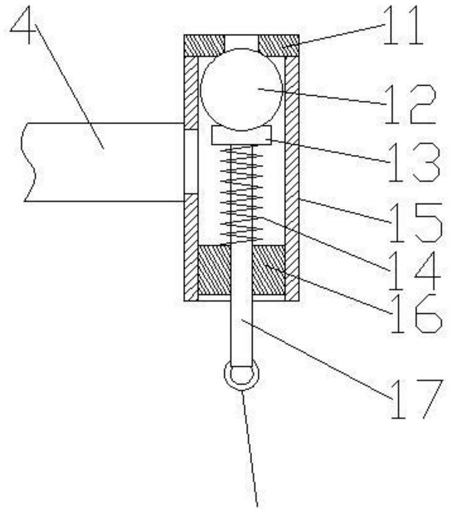
The invention provides a biogas digester safety pressure relief device. The biogas digester safety pressure relief device comprises a biogas tank and a slagging-off tank, wherein a communicating pipecommunicating with the slagging-off tank is arranged at the bottom of the biogas tank, a feeding pipe is arranged at the top of the biogas tank, a gas outlet pipe is arranged on the upper portion of the biogas tank and communicates with a pressure relief pipe, a sleeve is vertically fixed to the tail end of the pressure relief pipe, a V-shaped guide pipe is fixed to the bottom of the slagging-offtank, a pull rope is arranged in the guide pipe in a penetrating mode, a floating ball is fixed to one end of the pull rope, a sealing plate is fixed to the top of the sleeve, a fixing block is fixedto the bottom of the sleeve, a pull rod is vertically arranged in the fixing block in a penetrating mode, an ejector block is fixed to the top of the pull rod, the pull rod is sleeved with a spring, and a sealing ball is arranged on the upper portion of the ejector block. According to the device, a simple mechanical structure is adopted, no complex electrical equipment exists, automatic pressure relief of biogas is achieved, safety and reliability are achieved, and meanwhile, the trouble that cleaning is needed due to the fact that raw materials overflow out of the slagging-off tank is also omitted.

Description

technical field [0001] The invention relates to the technical field of biogas preparation, in particular to a safety pressure relief device for a biogas pit. Background technique [0002] Biogas is a mixed gas produced by the fermentation of organic matter by microorganisms under anaerobic conditions. The main raw materials for production are manure, straw and other crop waste. [0003] The biogas tank mainly consists of two parts, one is the main tank used to generate biogas, and the other is the slag removal tank connected to the bottom of the main tank. The residues in the main tank enter the slag removal tank and are cleaned regularly by workers. At present, in the process of use, it often occurs that the amount of biogas in the main tank is too large, which causes the air pressure in the main tank to increase, which is likely to cause danger. On the other hand, it also makes the main tank The raw materials in the body move to the slag removal tank, so that the residue ...

Claims


Application Information

Patent Timeline
IPC IPC(8): C12M1/107C12M1/00
CPCC12M21/04C12M29/20
Inventor 钱扬春
Owner 钱扬春
Learn More