A built-in partition type storage tank

A clapboard type and storage tank technology, applied in the direction of jet propulsion devices, rocket engine devices, machines/engines, etc., can solve the problems of unfavorable control trim, complex connection system design, small pipeline diameter, etc., and achieve simplified series-parallel design , Reduce system complexity, reduce the effect of design complexity

Active Publication Date: 2022-03-04
CHINA ACAD OF LAUNCH VEHICLE TECH
View PDF22 Cites 0 Cited by
  • Summary
  • Abstract
  • Description
  • Claims
  • Application Information

AI Technical Summary

Problems solved by technology

[0002] The air-to-earth reciprocating aircraft is distributed axisymmetrically. The ratio of the axial length to the radial dimension of the fuselage of this type of aircraft is relatively large, which determines that the ratio of the axial length to the radial dimension of the propellant tank is large. The consumption of propellant increases with the flight distance , the range of axial displacement of the remaining propellant in the tank is extremely large, resulting in severe sloshing of the remaining propellant in the tank, which affects the overall distribution of the center of mass of the aircraft, which is not conducive to exerting the aerodynamic advantage and is not conducive to the realization of controlled trim
[0003] Traditional launch vehicles mainly adopt the solution of large storage tanks in series / parallel connection of small storage tanks to store and manage the remaining propellant. The diameter of the pipelines between the tanks is small, the design of the connection system is complicated, and small-diameter one-way valve components are widely used. Not suitable for large-ton aerospace vehicles, the propellant flow control is not good, small tanks are easily collapsed by suction, and the layout of the tanks occupies the space of the aircraft

Method used


Image

  • A built-in partition type storage tank

Examples


Embodiment Construction

[0026] The present invention will be further elaborated below in conjunction with embodiment.

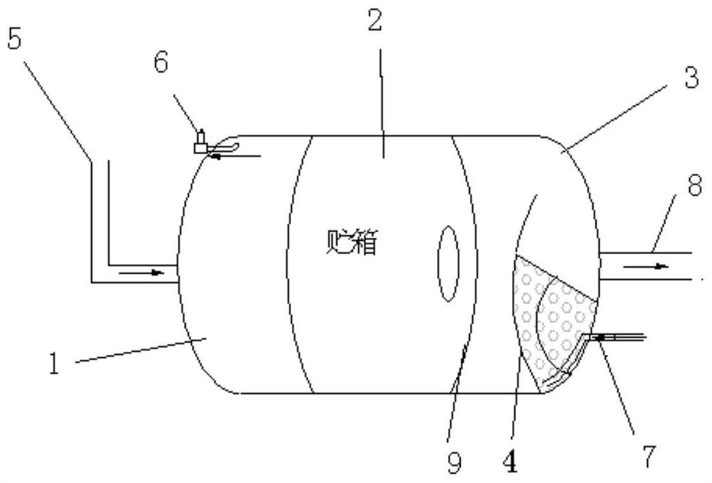
[0027] A built-in bulkhead storage tank, such as figure 1 As shown, it includes the front ellipsoid bottom, the cylinder section and the rear ellipsoid bottom, the front ellipsoid bottom and the rear ellipsoid bottom are connected with the cylinder section in the middle, and the three form a storage tank;

[0028] There are anti-shake plates and partitions inside the storage tank;

[0029] The anti-sway plate is an annular plate, which is installed on the inner wall of the cylinder section to prevent the propellant from shaking when the tank is full;

[0030] The partition is of partial spherical configuration, and is connected with the anti-sway plate adjacent to the bottom of the rear ellipsoid through screw connection, and the height of the partition is higher than the width of the anti-sway plate;

[0031] The propellant is injected through the filling pipeline at the bottom o...


PUM


Abstract

The invention relates to a built-in partition type storage tank, which comprises a front ellipsoidal bottom, a cylindrical tube section and a rear ellipsoidal bottom, and a cylindrical tube section is connected between the front ellipsoidal bottom and the rear ellipsoidal bottom, and the three form a storage tank; There are anti-sway plates and partitions inside the box; the anti-sway plates are ring-shaped plates, which are installed on the inner wall of the cylindrical section to prevent the propellant from shaking when the tank is full; The anti-sway plate at the bottom of the ellipsoid is connected and higher than the anti-sway plate; the propellant flows from the space above the partition to the bottom of the rear ellipsoid, and no fluid accumulation occurs in front of the partition; The plate suppresses the forward surge of the propellant, and the propellant is stored behind the partition to prevent the continuous change of the center of mass caused by the swaying of the mass. The storage tank of the present invention can be used for any type of propellant at normal temperature or low temperature, and the single-layer partition structure can realize the storage and management function of the remaining propellant in the storage tank, thereby reducing the use of one-way valves in the tank and reducing the complexity of pipeline system design Spend.

Description

technical field [0001] The invention relates to a built-in clapboard type storage tank, which belongs to the technical field of space-to-earth shuttle aircraft. Background technique [0002] The air-to-earth reciprocating aircraft is distributed axisymmetrically. The ratio of the axial length to the radial dimension of the fuselage of this type of aircraft is relatively large, which determines that the ratio of the axial length to the radial dimension of the propellant storage tank is large. The consumption of propellant increases with the flight range , the range of axial displacement of the remaining propellant in the tank is extremely large, resulting in severe sloshing of the remaining propellant in the tank, which affects the overall distribution of the center of mass of the aircraft, which is not conducive to exerting the aerodynamic advantage and is not conducive to the realization of controlled trim. [0003] The traditional launch vehicle mainly adopts the solution ...

Claims


Application Information

Patent Timeline
Patent Type & Authority Patents(China)
IPC IPC(8): F02K9/60
CPCF02K9/605
Inventor 田晓旸陈亮郑平军王飞蔡巧言粆安安马婷婷吴莉莉袁园张晓帆张斌宋国莲孙兵赵建波韩威
Owner CHINA ACAD OF LAUNCH VEHICLE TECH
Why Eureka
Try Eureka