
Main bearing cover

A technology for main bearing caps and bearing caps, applied in bearings, bearing assembly, bearing components, etc., can solve the problems of high assembly requirements for assemblers, low efficiency of disassembly and assembly, and affect normal use, so as to avoid damage, improve installation efficiency, The effect of improving accuracy

Active Publication Date: 2021-03-09
NINGBO HAINA MACHINERY
View PDF5 Cites 0 Cited by
  • Summary
  • Abstract
  • Description
  • Claims
  • Application Information

AI Technical Summary

Problems solved by technology

[0003] In the prior art, the bearing cap and the bearing seat are usually connected by bolts. On the one hand, the bolt connection needs to be equipped with special tools for disassembly, and considering that the assembly of the bearing cap and the bearing seat needs to withstand the impulse from the engine, it is difficult for the assembler. High assembly requirements lead to low disassembly efficiency; on the other hand, due to the bolt connection, the crankshaft and the main bearing cap often have an interference fit, so when the vehicle vibrates or collides, the crankshaft will be caused by the interference fit. damage, thus affecting its normal use

Method used


Image

  • Main bearing cover
  • Main bearing cover
  • Main bearing cover

Examples


Embodiment Construction

[0037] Hereinafter, the present application will be further described in conjunction with specific implementation methods. It should be noted that, on the premise of not conflicting, the various embodiments or technical features described below can be combined arbitrarily to form new embodiments.

[0038] In the description of this application, it should be noted that for orientation words, such as the terms "center", "horizontal", "longitudinal", "length", "width", "thickness", "upper", "lower" , "Front", "Back", "Left", "Right", "Vertical", "Horizontal", "Top", "Bottom", "Inner", "Outer", "Clockwise", "Counterclockwise ” and other indication orientations and positional relationships are based on the orientations or positional relationships shown in the drawings, which are only for the convenience of describing the application and simplifying the description, rather than indicating or implying that the device or element referred to must have a specific orientation, use a specifi...


PUM


Abstract

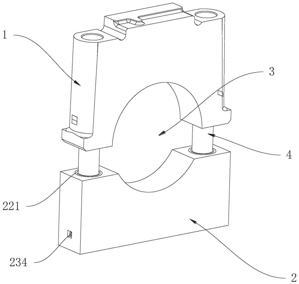
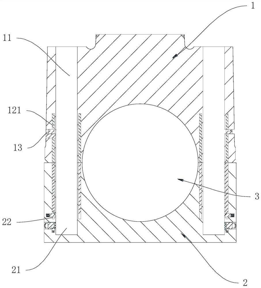
The invention discloses a main bearing cover. The main bearing cover comprises connecting columns; through holes are formed in the bearing cover; first openings are formed in the positions, corresponding to the through holes, of a bearing seat; the connecting columns are inserted into the through holes and the first openings to be connected with the bearing cover; a first containing cavity, a first permanent magnet and a first limiting block are arranged in the bearing cover; the first containing cavity allows the first permanent magnet to slide therein; the first limiting block limits the movement of the first permanent magnet; a second containing cavity and a second permanent magnet are arranged in the bearing seat; and the second containing cavity allows the second permanent magnet to slide therein and is suitable for the first permanent magnet to slide therein. According to the main bearing cover, the pre-assembly of the bearing cover and the bearing seat can be finished in the assembly process, so that the assembly mode of the bearing seat and the bearing cover is simplified, the disassembly efficiency is improved; and a crankshaft can be prevented from moving between the transverse direction and the longitudinal direction, and the impact force can be effectively reduced and the crankshaft can be prevented from being damaged during the vibration and collision of a vehicle.

Description

technical field [0001] The present application relates to the technical field of engine components, in particular to a main bearing cap. Background technique [0002] The main bearing cap is installed on the cylinder block of the car, and the parts of the main journal of the crankshaft are fixed together by the main bearing cap and the cylinder block, thereby preventing radial movement of the crankshaft during operation. [0003] In the prior art, the bearing cap and the bearing seat are usually connected by bolts. On the one hand, the bolt connection needs to be equipped with special tools for disassembly, and considering that the assembly of the bearing cap and the bearing seat needs to withstand the impulse from the engine, it is difficult for the assembler. High assembly requirements lead to low disassembly efficiency; on the other hand, due to the bolt connection, the crankshaft and the main bearing cap often have an interference fit, so when the vehicle vibrates or col...

Claims


Application Information

Patent Timeline
Patent Type & Authority Applications(China)
IPC IPC(8): F16C35/00F16B21/10F16B21/16F02F7/00
CPCF16C35/00F16B21/10F16B21/16F02F7/0053F16C2360/22F16C2226/00F16C2226/62F16C2226/70F16B2200/83
Inventor 张宏勇赖挺松孙月芬吴建贤
Owner NINGBO HAINA MACHINERY
Learn More