Lighting device of microwave sulfur lamp
A technology for lighting devices and sulfur lamps, applied in lighting devices, lighting devices, fixed lighting devices, etc., can solve problems such as poor contact, loose lines, and support frames that cannot be changed according to actual needs, so as to achieve stable connections and improve The effect of practicality
- Summary
- Abstract
- Description
- Claims
- Application Information
AI Technical Summary
Problems solved by technology
Method used
Image
Examples
Embodiment 1
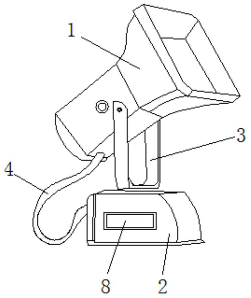
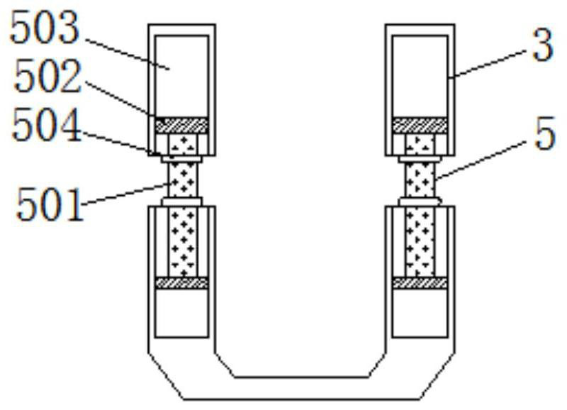
[0027] Such as Figure 1-Figure 4 As shown, the present invention provides a lighting device for a microwave sulfur lamp, which includes a sulfur lamp lighting body 1, a placement seat 2, a support frame 3, a connecting wire 4, a bracket adjustment mechanism 5, an adjustment rod 501, a first guide block 502, First guide groove 503, retaining collar 504, wire body retaining mechanism 6, retaining plate 601, first slider 602, first chute 603, first movable part 604, rotating rod 605, second movable part 606, the second slider 607, the second chute 608, the first spring 609, the space adjustment mechanism 7, the adjustment plate 701, the second guide block 702, the second guide groove 703, the positioning bolt 704, the strip plate 705 and place box of 8.
[0028] Preferably, in one of the preferred technical solutions of this embodiment, the bottom of the sulfur lamp body 1 is provided with a placement seat 2; a support frame 3 is connected between the placement seat 2 and the s...
Embodiment 2
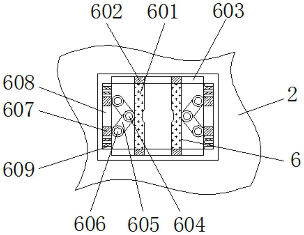
[0032] Such as image 3 As shown, the difference between this embodiment and the foregoing embodiment is that;
[0033] The inside of the wire body retaining mechanism 6 includes a retaining plate 601; the outside of the retaining plate 601 is equipped with a first slide block 602, and the outside of the first slide block 602 is provided with a first chute 603, and the retaining plate 601 The outer side is connected with a first movable part 604; the outside of the first movable part 604 is equipped with a rotating rod 605, and the outer side of the rotating rod 605 is connected with a second movable part 606; the outer part of the second movable part 606 is installed with a second Slider 607, the outside of the second slider 607 is provided with a second chute 608; the inside of the second chute 608 is equipped with a first spring 609, wherein the second chute 608 is equipped with a first spring 609, then The retaining plate 601 is effectively reset, thereby effectively reta...
Embodiment 3
[0038] Such as Figure 4 As shown, the difference between this embodiment and the foregoing embodiment is that;
[0039] The inside of the space adjustment mechanism 7 includes an adjustment plate 701; the outside of the adjustment plate 701 is equipped with a second guide block 702, the outside of the second guide block 702 is provided with a second guide groove 703, and the inside of the adjustment plate 701 is screwed with a positioning Bolt 704; the outside of described positioning bolt 704 is provided with strip plate 705, and wherein strip plate 705 adopts two groups and placement box 8 to fix; Preset strip groove between described two strip plate 705, then makes The positioning bolt 704 is effectively tightened by transposition.
[0040] Such as Figure 4 As shown, in one of the preferred technical solutions of this embodiment, the adjustment plate 701 forms a movable structure through the second guide block 702, the second guide groove 703 and the placement box 8; th...
PUM
 Abstract
Description
Claims
Application Information
 - R&D
- Intellectual Property
- Life Sciences
- Materials
- Tech Scout
- Unparalleled Data Quality
- Higher Quality Content
- 60% Fewer Hallucinations
Browse by: Latest US Patents, China's latest patents, Technical Efficacy Thesaurus, Application Domain, Technology Topic, Popular Technical Reports.
© 2025 PatSnap. All rights reserved.Legal|Privacy policy|Modern Slavery Act Transparency Statement|Sitemap|About US| Contact US: help@patsnap.com


