Supercharge Your Innovation With Domain-Expert AI Agents!

High-resolution solid-state area array laser radar system, control method and device

A high-resolution, lidar technology, applied in the field of photoelectric detection, can solve the problems of high volume power consumption, difficult manufacturing cost, cost increase, etc., and achieve the effect of promoting wide application, small volume power consumption, and improving resolution

Pending Publication Date: 2021-03-09
中航航空电子有限公司
View PDF6 Cites 1 Cited by
  • Summary
  • Abstract
  • Description
  • Claims
  • Application Information

AI Technical Summary

Problems solved by technology

[0004] Limited by the process and material technology, the resolution of the APD array detector used in the existing technology is difficult to improve rapidly in the short term. The resolution of the existing APD array is about 10*10, which is difficult to meet the needs of high-resolution laser detection.
The manufacture of high-resolution APD arrays is extremely difficult, and the cost is increased by orders of magnitude. At the same time, high-resolution APD arrays also sharply increase the size and power consumption of the back-end receiving and processing circuits, which limits the area array solid-state lidar. Extremely high technical difficulty, huge volume power consumption and high manufacturing cost are difficult to be widely promoted and applied

Method used


Image

  • High-resolution solid-state area array laser radar system, control method and device
  • High-resolution solid-state area array laser radar system, control method and device
  • High-resolution solid-state area array laser radar system, control method and device

Examples


Embodiment Construction

[0027] In order to make the object, technical solution and advantages of the present invention clearer, the present invention will be further described in detail below in conjunction with the accompanying drawings and embodiments. It should be understood that the specific embodiments described here are only used to explain the present invention, not to limit the present invention.

[0028] It can be understood that the terms "first", "second" and the like used in the present application may be used to describe various elements herein, but unless otherwise specified, these elements are not limited by these terms. These terms are only used to distinguish one element from another element. For example, a first xx script could be termed a second xx script, and, similarly, a second xx script could be termed a first xx script, without departing from the scope of the present application.

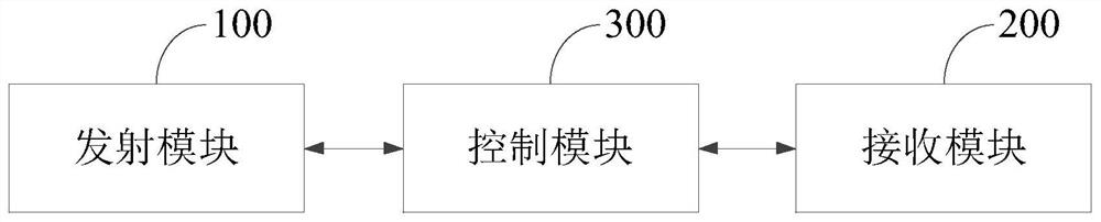
[0029] figure 1 It shows a structural block diagram of a high-resolution solid-state array las...


PUM


Abstract

The invention relates to the technical field of photoelectric detection, in particular to a high-resolution solid-state area array laser radar system, a control method and a control device, and the high-resolution solid-state area array laser radar system comprises: a transmitting module which is used for generating laser and transmitting the laser; a receiving module which is used for receiving the laser reflected by the detected object, wherein the receiving module comprises an echo detector and a scanner capable of moving along an optical axis, and the position of the laser irradiated to the echo detector can be changed by moving the position of the scanner; and a control module, wherein the control module is respectively connected with the transmitting module and the receiving module,and is used for controlling the work of the transmitting module and the receiving module, and synthesizing at least two reflection images of the same measured object acquired by the scanner into an image of the measured object. By arranging the movable scanner, multi-point multi-time detection of a target can be achieved, so that high-resolution detection imaging is achieved, the cost is low, andimplementation is easy.

Description

technical field [0001] The invention relates to the field of photoelectric detection technology, in particular to a high-resolution solid-state area array laser radar system, a control method and a device. Background technique [0002] As the core sensor of robots and unmanned driving, the importance of lidar is self-evident. At present, lidar can be divided into mechanical lidar and solid-state lidar according to whether there are mechanical parts or not. Among them, the mechanical lidar has rotating parts to control the laser emission angle, while the solid-state lidar does not need mechanical rotating parts, and mainly relies on electronic components to control the laser emission angle. Compared with mechanical lidar, solid-state lidar is small in size, cheap in cost, and applicable to a wider range of scenarios. [0003] Solid-state lidar is mainly composed of lasers, collimating optical paths, mirrors, Damman gratings, hollow mirrors, laser echo receiving and processin...

Claims


Application Information

Patent Timeline
Patent Type & Authority Applications(China)
IPC IPC(8): G01S17/89G01S7/481
CPCG01S17/89G01S7/4817
Inventor 范大勇黄涛
Owner 中航航空电子有限公司
Features
  • R&D
  • Intellectual Property
  • Life Sciences
  • Materials
  • Tech Scout
  • Unparalleled Data Quality
  • Higher Quality Content
  • 60% Fewer Hallucinations
Learn More