
A novel circularly polarized millimeter-wave broadband planar reflectarray antenna with feedforward excitation and multi-frequency points

A plane reflection, array antenna technology, applied in the microwave field, can solve the problems of increased loss, complexity, and high processing accuracy requirements in the millimeter wave band, and achieve the effect of increasing gain and increasing bandwidth

Active Publication Date: 2021-12-28
XIAMEN UNIV
View PDF23 Cites 0 Cited by
  • Summary
  • Abstract
  • Description
  • Claims
  • Application Information

AI Technical Summary

Problems solved by technology

Large-scale reflector antennas are simple in design, theoretically infinite in gain bandwidth, and have high efficiency and strong directivity, but they are bulky and difficult to deploy, requiring a complex servo system. The curved surface structure requires high processing accuracy, especially in the millimeter wave band. , beam scanning can only be achieved by mechanical rotation is also a disadvantage
Microstrip patch array antennas often have a low profile, and PCB etching technology is mature. The phase and amplitude of the radiating element can be adjusted independently by phase shifting, and it is easy to realize beam scanning. However, for ultra-large-scale arrays, the design of the feed network is complicated. The cost of T / R components required for electronic scanning is high, and the loss of the millimeter wave band increases sharply

Method used


Image

  • A novel circularly polarized millimeter-wave broadband planar reflectarray antenna with feedforward excitation and multi-frequency points
  • A novel circularly polarized millimeter-wave broadband planar reflectarray antenna with feedforward excitation and multi-frequency points
  • A novel circularly polarized millimeter-wave broadband planar reflectarray antenna with feedforward excitation and multi-frequency points

Examples


Embodiment Construction

[0037] The following embodiments will further illustrate the present invention in conjunction with the accompanying drawings.

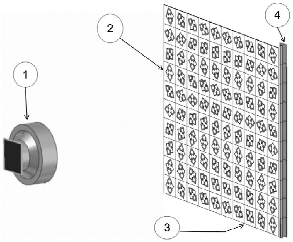
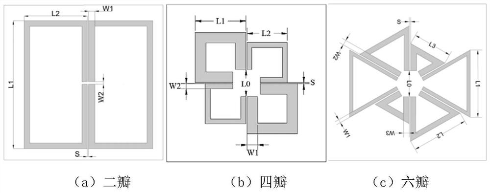
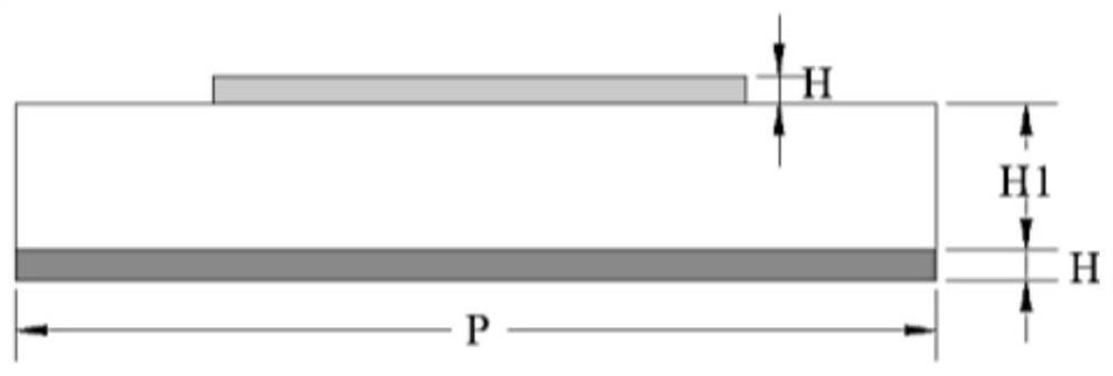
[0038] like Figure 1~3 , the embodiment of the present invention is provided with a dielectric substrate 3, the upper surface of the dielectric substrate 3 is provided with a microstrip n*n petal reflective array 2, and the back of the dielectric substrate is provided with a ground plate 4, and the outline of the ground plate 4 is rectangular; satisfying the recursive relationship and uniform arrangement The microstrip n*n petal reflector array is distributed on the upper surface in a rotation pattern at a certain angle, and the surface of the microstrip n*n petal reflector array faces the feed source 1 of the horn antenna. By controlling the angle ψ that the tightly coupled petal unit rotates counterclockwise along the center of each petal itself mn The purpose of reflection phase delay can be achieved, and the required compensation phase can be ob...


PUM


Abstract

The invention relates to a novel circularly polarized millimeter-wave broadband planar reflective array antenna with multi-frequency points for feedforward excitation, and belongs to the field of microwave technology. It includes a dielectric substrate, a ground plane, a feed source, and a microstrip n*n petal reflection array; the microstrip n*n petal reflection array includes n*n single-layer tightly coupled petal units, and n*n single-layer tightly coupled petal units The units meet the recursive relationship and are evenly arranged on the upper surface of the dielectric substrate and are distributed at a certain angle. The microstrip n*n petal reflector array faces the feed source; each tightly coupled petal unit is a circle containing 2*M pairs of equal sizes. Regular polygon split resonant rings with regular 2*M polygon gaps, and regular polygon split resonant rings of different sizes work at different frequencies respectively to form a multi-resonant unit; a ground plate is provided on the back of the dielectric substrate, and the outline of the ground plate is rectangular. Capable of working in different millimeter wave bands including 5G specifications, designed on demand, has good radiation performance, simple structure, low cost, and easy engineering implementation.

Description

technical field [0001] The invention belongs to the field of microwave technology, and in particular relates to a novel circularly polarized millimeter-wave broadband planar reflection array antenna with forward-feed excitation and multi-frequency points. Background technique [0002] Traditional high-gain antennas mainly include reflector antennas represented by large parabolic antennas and microstrip patch array antennas represented by phased array antennas. Large-scale reflector antennas are simple in design, theoretically infinite in gain bandwidth, and have high efficiency and strong directivity, but they are bulky and difficult to deploy, requiring a complex servo system. The curved surface structure requires high processing accuracy, especially in the millimeter wave band. , beam scanning can only be achieved by mechanical rotation is also a disadvantage. Microstrip patch array antennas often have a low profile, and PCB etching technology is mature. The phase and amp...

Claims


Application Information

Patent Timeline
Patent Type & Authority Patents(China)
IPC IPC(8): H01Q21/06H01Q1/38
CPCH01Q21/065H01Q1/38
Inventor 游佰强陈奇游京霖贺显慧聂敬李伟文
Owner XIAMEN UNIV
Learn More