Passive optical splitter port state monitoring device and passive optical splitter port state monitoring method

A passive optical splitter and port status technology, applied in the field of optical splitters, can solve problems affecting the operating efficiency and stability of optical splitters, lack of protective measures for monitors, poor integrity, etc., to achieve easy operation, high disposal efficiency, The effect of maintaining stability

Pending Publication Date: 2021-03-09
南京宏之图信息技术有限公司
View PDF0 Cites 0 Cited by
  • Summary
  • Abstract
  • Description
  • Claims
  • Application Information

AI Technical Summary

Problems solved by technology

[0004] The main purpose of the present invention is to provide a monitoring device and monitoring method for the port state of a passive optical splitter, so as to solve the problem that the current monitoring method for the port state of a passive optical splitter has poor operation integrity, takes a long time to deal with the problem, and affects the optical splitter. The operating efficiency and stability of the monitor, and the use of the monitor lacks certain protective measures, etc.

Method used


Image

  • Passive optical splitter port state monitoring device and passive optical splitter port state monitoring method
  • Passive optical splitter port state monitoring device and passive optical splitter port state monitoring method
  • Passive optical splitter port state monitoring device and passive optical splitter port state monitoring method

Examples


Embodiment 1

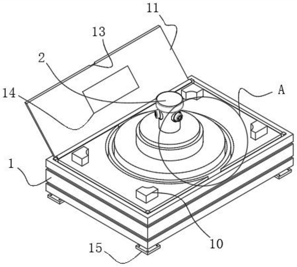
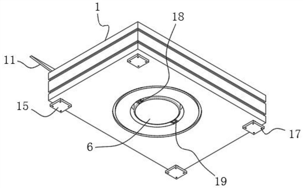
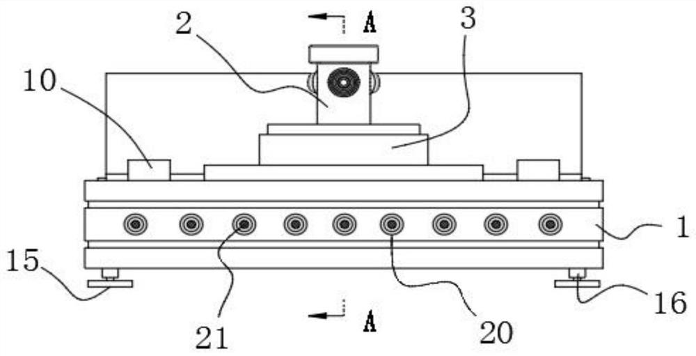
[0037] Please refer to Figure 1-5 Shown: a monitoring device for the port status of a passive optical splitter, including a housing 1 and a monitor 2, the housing 1 is provided with a monitor 2, the upper surface of the housing 1 is provided with an upper groove 8, and an upper groove 8 Mounting seat 4 is installed inside, the upper surface of mounting seat 4 is connected with turntable 3, the bottom end of monitor 2 is connected with turntable 3, the bottom end of housing 1 is provided with lower groove 9, and cooling fan 6 is installed inside lower groove 9, The output end of the heat dissipation fan 6 is connected with an air guide pipe 7, one end of the air guide pipe 7 is adapted to the upper groove 8, the two opposite side surfaces of the heat dissipation fan 6 are connected with sliders 18, and the side surfaces of the lower groove 9 are equipped with slide rails 19. The slider 18 is compatible with the slide rail 19, and the slider 18 is slidingly matched with the sli...

Embodiment 2

[0040] Please refer to Figure 6 Shown: the monitoring method of described passive optical splitter port state, comprises the steps:

[0041] Step 1: Insert the plugs 21 into all the interfaces 20 of the passive optical splitter;

[0042] Step 2: Set the standard value of the interface state, so that each interface can maintain the operating state under the standard value synchronously;

[0043] Step 3: Collect information on the running status of a single interface, and keep the other interfaces in normal running status during the collection process;

[0044]Step 4: Compare the information of the acquisition interface with the status of other interfaces, that is, compare with the standard value;

[0045] Step 5: When the plug of the monitoring equipment is pulled out from the passive optical splitter, the system can record this information in real time, and can give an alarm in real time according to the specified rules, and the system will notify the operator to perform im...


PUM


Abstract

The invention discloses a passive optical splitter port state monitoring device and a passive optical splitter port state monitoring method, and relates to the technical field of optical splitters. The passive optical splitter port state monitoring device comprises a shell and a monitor, the monitor is arranged in the shell, an upper groove is formed in the upper surface of the shell, a mounting seat is mounted in the upper groove, and a rotary disc is connected to the upper surface of the mounting seat; the bottom end of the monitor is connected with the rotary disc, a lower groove is formedin the bottom end of the shell, a cooling fan is installed in the lower groove, the output end of the cooling fan is connected with an air guide pipe, one end of the air guide pipe is matched with theupper groove, sliding blocks are connected to the two opposite side surfaces of the cooling fan, and sliding rails are installed on the side surfaces of the lower groove and matched with the slidingblocks. The sliding block is in sliding fit with the sliding rail, and a cover plate is further installed on one side of the upper surface of the shell. By monitoring the state of the monitor port, the passive optical splitter is kept in a stable operation state, the passive optical splitter port can be effectively prevented from being accessed by unauthorized equipment, and the network security can be effectively improved.

Description

technical field [0001] The invention relates to the technical field of optical splitters, in particular to a monitoring device and a monitoring method for a port state of a passive optical splitter. Background technique [0002] An optical splitter is a passive device, also known as an optical splitter, they do not require external energy, as long as there is input light, an optical splitter is a fiber optic junction device with multiple input ports and multiple output ports, commonly used For the coupling, branching and distribution of optical signals, in the mobile communication network, the monitor is used as a special probe for signaling monitoring, which mainly realizes the original signaling data collection, cooperates with the signaling analysis system, and performs real-time monitoring and in-depth fault location on the network , to provide strong support for network maintenance, market, and customers, and to realize the evaluation of network and service quality and ...

Claims


Application Information

Patent Timeline
Patent Type & Authority Applications(China)
IPC IPC(8): H04Q11/00H04Q1/02H04Q1/04F16M11/08F16M11/20
CPCF16M11/08F16M11/20H04Q1/035H04Q1/04H04Q11/0067H04Q11/0071H04Q2011/0083
Inventor 曹海涛
Owner 南京宏之图信息技术有限公司
Why Eureka
Try Eureka