Precision stamping equipment

A precision stamping and equipment technology, applied in metal processing equipment, feeding devices, manufacturing tools, etc., can solve problems such as movement

Inactive Publication Date: 2021-03-12
马鞍山威泰机电有限公司
View PDF1 Cites 3 Cited by
  • Summary
  • Abstract
  • Description
  • Claims
  • Application Information

AI Technical Summary

Problems solved by technology

[0006] Aiming at the deficiencies of the prior art, the present invention provides a precision stamping equipment capable of limiting and positioning the four corners of the stamping part during stamping, preventing the workpiece from shifting during stamping, and at the same time, the limit mechanism does not cause damage to the stamping work of the stamping equipment. The advantage of the impact, solves the problem that the setting of the limit device will have a certain impact on stamping, and at the same time only through the limit on both sides, the stamping parts may move in the front and rear directions during stamping

Method used


Image

  • Precision stamping equipment
  • Precision stamping equipment
  • Precision stamping equipment

Examples


Embodiment Construction

[0024] The following will clearly and completely describe the technical solutions in the embodiments of the present invention with reference to the accompanying drawings in the embodiments of the present invention. Obviously, the described embodiments are only some, not all, embodiments of the present invention. Based on the embodiments of the present invention, all other embodiments obtained by persons of ordinary skill in the art without making creative efforts belong to the protection scope of the present invention.

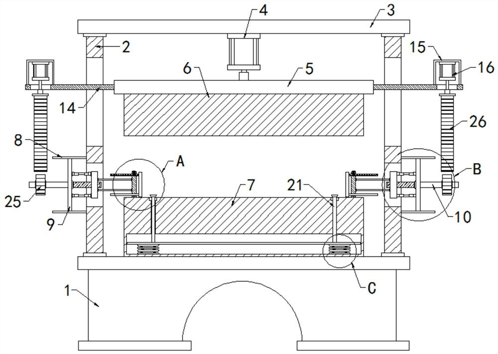
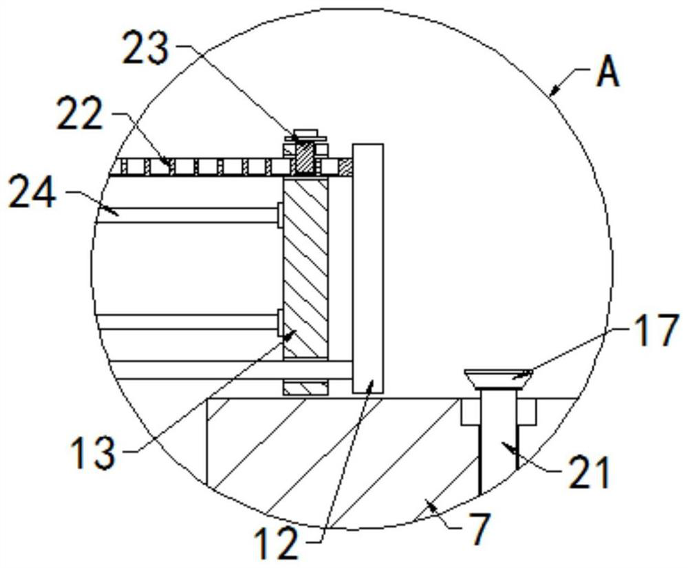
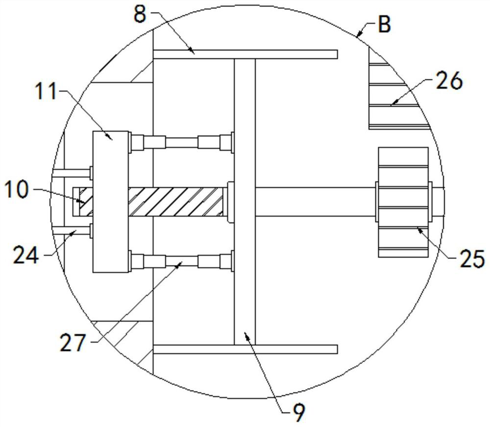
[0025] see Figure 1-4 , a kind of precision stamping equipment, comprising a base 1, two symmetrically arranged support plates 2 are fixed on the top of the base 1, a top plate 3 is fixed on the top of the two support plates 2, and a hydraulic pressure is fixed on the bottom of the top plate 3. Cylinder 4, the bottom of the piston rod of the hydraulic cylinder 4 is fixed with a push plate 5, the bottom of the push plate 5 is fixed with an upper template 6, th...


PUM


Abstract

The invention relates to the technical field of stamping equipment, and discloses precision stamping equipment which comprises a base. Two symmetrically-arranged supporting plates are fixedly arrangedat the top of the base; a top plate is fixedly arranged at the tops of the two supporting plates; a hydraulic cylinder is fixedly arranged at the bottom of the top plate; a push plate is fixedly arranged at the bottom of a piston rod of the hydraulic cylinder; an upper die plate is fixedly arranged at the bottom of the push plate; a lower die plate is fixedly arranged at the top of the base; a cavity is formed in the lower end of the interior of the lower die plate; an adsorption rebound mechanism is arranged in the cavity; a first sliding groove and a second sliding groove are formed in theupper ends and the lower ends of the two supporting plates correspondingly; fixing plates are fixedly arranged on the sides, away from each other, of the two supporting plates and located on the two sides of the second sliding groove; and a vertical plate is fixedly arranged between the two fixing plates. According to the precision stamping equipment, the four corners of a stamped part can be limited and positioned in the stamping process, and a workpiece is prevented from moving in the stamping process.

Description

technical field [0001] The invention relates to the technical field of stamping equipment, in particular to precision stamping equipment. Background technique [0002] Stamping is to apply external force to plates, strips, pipes and profiles by presses and molds to cause plastic deformation or separation, so as to obtain workpieces of required shape and size. Stamping is an existing processing and production method. Mainstream processing method. [0003] Wherein the patent number is CN211539155U discloses a kind of precision stamping device, this device limits the precision workpiece on the lower mold by adding a precision workpiece limit mechanism, so the probability of the occurrence of positional deviation of the precision workpiece can be reduced, That is to say, the probability of deviation in the punching position of the precision workpiece is reduced, thereby improving the reliability of the precision stamping device, but there are certain defects in the use of the d...

Claims


Application Information

Patent Timeline
Patent Type & Authority Applications(China)
IPC IPC(8): B21D22/02B21D43/00
CPCB21D22/02B21D43/003
Inventor 刘旭庆
Owner 马鞍山威泰机电有限公司
Why Eureka
Try Eureka