Transition chain plate bending method

A chain plate and bending forming technology, applied in the field of chain transmission, can solve the problems of poor forming effect of transition chain plates, and achieve the effect of shortening maintenance time, improving bending quality and work efficiency

Pending Publication Date: 2021-03-12
QINGDAO CHOHO IND CO LTD
View PDF0 Cites 0 Cited by
  • Summary
  • Abstract
  • Description
  • Claims
  • Application Information

AI Technical Summary

Problems solved by technology

[0008] In order to solve the problems existing in the prior art, the present invention provides a bending method of the transition chain plate, which changes the technical prejudice of the prior art. When stamping the transition chain plate, only the plane structures on both sides are stamped, The slope structure is formed naturally. Through the above improvements, the problem of poor forming effect of the transition chain plate is solved.

Method used


Image

  • Transition chain plate bending method
  • Transition chain plate bending method
  • Transition chain plate bending method

Examples


Embodiment 1

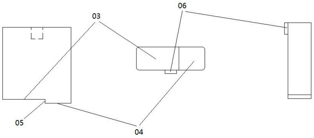
[0033] A bending method of a transition link plate, comprising the step of simultaneously stamping the planar structures on both sides of the transition link plate using a mold, and in the step, the slope structure of the transition link plate is formed naturally.

[0034] In this embodiment, by allowing the inclined structure 02 to form naturally, the mutual interference between the planar structure 01 and the inclined structure 02 during the stamping process can be effectively avoided, so that the transition link plate can obtain a better forming effect.

Embodiment 2

[0036] On the basis of Embodiment 1, this embodiment discloses the specific structure of the bending forming punch:

[0037] Such as image 3 , 4As shown, a kind of bending forming punch used in the bending method of a transitional chain plate includes an upper bending forming punch 12 and a lower bending forming punch 13, and the upper bending forming punch 12 A first plane C03 and a second plane C04 are provided on the lower end surface of the bottom surface, and a vertical plane C05 is connected between the first plane C03 and the second plane C04. The upper end surface of the lower bending forming punch 13 is provided with a second plane C04. A plane D07 and a second plane D08, a vertical plane D016 is connected between the first plane D07 and the second plane D08, the first plane C03 and the first plane D07 cooperate with each other to stamp the transition chain The plane structure on one side of the plate, the second plane C04 and the second plane D08 cooperate with ea...

Embodiment 3

[0042] On the basis of embodiment 2, this embodiment discloses the concrete structure of the mold that is provided with bending forming punch:

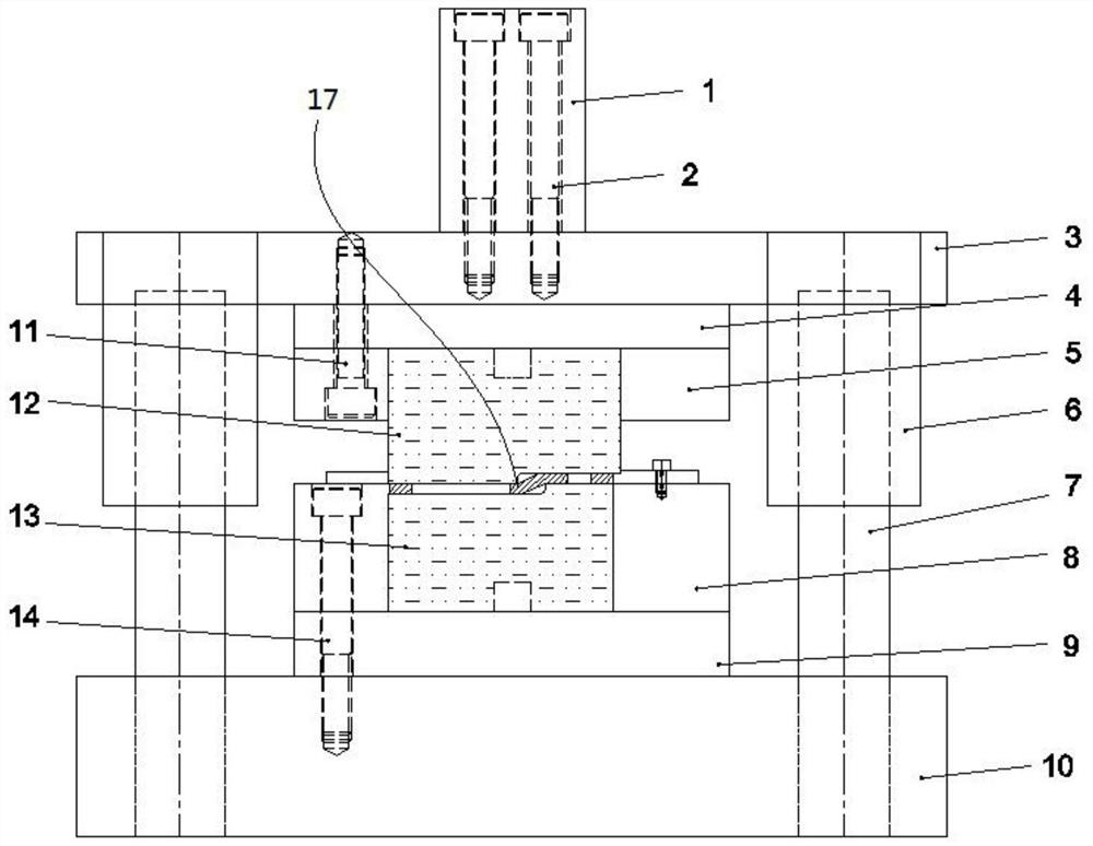
[0043] Such as figure 1 , 2 , as shown in 9:

[0044] A mold for a bending forming punch is provided, including an upper die and a lower die, the upper die is equipped with an upper bending forming punch 12, and the lower die is equipped with a lower bending forming punch 13, and the upper die is equipped with a lower bending forming punch 13. The upper bending forming punch 12 is used in conjunction with the lower bending forming punch 13;

[0045] The upper die includes a mold handle 1, an upper template 3, an upper backing plate 4, and an upper fixing plate 5 from top to bottom, and the lower mold includes a lower template 10, a lower backing plate 9, and a lower backing plate from bottom to top. The fixed plate 8, the two sides of the lower end surface of the upper template 3 are respectively provided with guide sleeves 6, the...


PUM


Abstract

The invention provides a transition chain plate bending method, and relates to the technical field of chain transmission. The transition chain plate bending method comprises the steps of simultaneously stamping plane structures of a transition chain plate by using a die, specifically, inclined plane structures of the transition chain plate are naturally formed; a bending forming punch comprises anupper bending forming punch body and a lower bending forming punch body, a first plane C, a vertical plane A and a second plane C are arranged at the lower end of the upper bending forming punch body, and a first plane D, a vertical plane B and a second plane D are arranged at the upper end of the lower bending forming punch body; and the die comprises an upper die body and a lower die body, theupper bending forming punch body is installed on the upper die body, the lower bending forming punch body is installed on the lower die body, and the upper bending forming punch body and the lower bending forming punch body are used in cooperation. According to the transition chain plate bending method, the technical prejudice in the prior art is changed, when the transition chain plate is punched, only the plane structures on the two sides are punched, the inclined plane structures are naturally formed, and through the improvement, the problem that the forming effect of the transition chain plate is poor is solved.

Description

technical field [0001] The invention relates to the technical field of chain transmission, in particular to a bending method of a transition chain plate. Background technique [0002] The transition chain plate (OFD chain plate) is mainly used in the transition chain link. When designing the center distance of the chain transmission, when the design requirements cannot avoid the chain being an odd number of chain links, it is necessary to use the transition chain link and the composite transition chain link, and the composite transition chain link The transition link is better than the transition link. The composite transition link is riveted by a standard inner single section and a transition link with a pin, and the transition link is an interference fit between two transition link plates and a sleeve. [0003] Such as Figure 8 As shown, it is the front view and top view of the transition chain plate of the baler chain. It can be seen from the figure that the transition c...

Claims


Application Information

Patent Timeline
IPC IPC(8): B21L9/04B21D37/10B21D37/12B21D37/04
CPCB21L9/04B21D37/10B21D37/12B21D37/04
Inventor 金玉谟冷路娜朱汉恩尚文帅刘天才许全全
Owner QINGDAO CHOHO IND CO LTD
Why Eureka
Try Eureka