
3D printing screw placement guide fixture

A technology for printing screws and placing nails, which is applied to dispensing devices, manufacturing tools, nail dispensers, etc., can solve problems such as easy loss and inconvenience, and achieve the effects of avoiding loss, strong practicability and reasonable design.

Inactive Publication Date: 2021-03-12
夏磊
View PDF5 Cites 0 Cited by
  • Summary
  • Abstract
  • Description
  • Claims
  • Application Information

AI Technical Summary

Problems solved by technology

[0003] The existing 3D-printed nail setting fixture is composed of two rings, which are hinged and fixed by a bolt during installation. However, after the bolt is taken out, the bolt needs to be placed, which is easy to lose and is inconvenient. To this end, we propose a 3D printed screw guide fixture

Method used


Image

  • 3D printing screw placement guide fixture
  • 3D printing screw placement guide fixture
  • 3D printing screw placement guide fixture

Examples


Embodiment Construction

[0015] The present invention will be further described below in conjunction with specific examples. It should be understood that these examples are only used to illustrate the present invention and are not intended to limit the scope of the present invention. In addition, it should be understood that after reading the teachings of the present invention, those skilled in the art can make various changes or modifications to the present invention, and these equivalent forms also fall within the scope defined by the appended claims of the application.

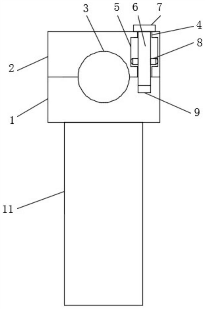
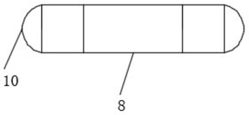
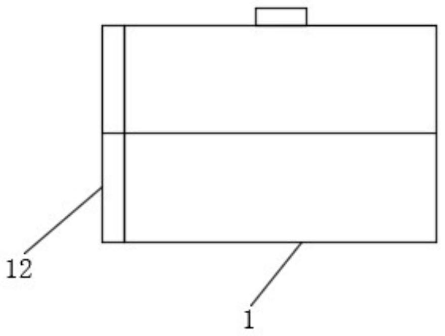
[0016] see figure 1 , figure 2 with image 3 It is a schematic diagram of the structure of the present invention, a 3D printing screw setting guide fixture, including a first clamping block 1, the top left end of the first clamping block 1 is hinged with a second clamping block 2, the first clamping block 1 and the second clamping block Clamp holes 3 are provided between the blocks 2, the combined displacement of the first clamp...


PUM


Abstract

The invention discloses 3D printing screw placement guide fixture. The fixture comprises a first clamping block, a second clamping block is hinged to the left end of the top of the first clamping block, a clamping hole is formed between the first clamping block and the second clamping block, a threaded groove is formed at the right side of the top of the first clamping block, a circular hole is formed at the right side of the top of the second clamping block, and an annular groove is formed in the inner side wall of the circular hole; and a threaded rod is arranged in the circular hole, a cylindrical block is fixedly installed at the top end of the threaded rod, a circular ring is fixedly installed on the side wall of the threaded rod, the circular ring is located in the annular groove, and the bottom end of the threaded rod is connected into the threaded groove in a threaded manner. The threaded groove is formed in the first clamping block, the threaded rod is arranged on the second clamping block, the circular ring is arranged on the side wall of the threaded rod, the circular ring is located in the inner annular groove of the second clamping block, after the threaded rod is separated from the threaded groove, the circular ring is located in the annular groove, the threaded rod cannot be separated from the second clamping block, the integral effect of the threaded rod and thewhole body is improved, loss of parts is avoided, design is reasonable, and practicability is higher.

Description

technical field [0001] The invention relates to the field of jigs, in particular to a 3D printing screw setting guide jig. Background technique [0002] 3D printing (3DP) is a kind of rapid prototyping technology. It is a technology based on digital model files and using bondable materials such as powdered metal or plastic to construct objects by layer-by-layer printing. 3D printing is usually achieved using digital technology material printers. [0003] The existing 3D-printed nail setting fixture is composed of two rings, which are hinged and fixed by a bolt during installation. However, after the bolt is taken out, the bolt needs to be placed, which is easy to lose and is inconvenient. To this end, we propose a 3D printed screw guide fixture. Contents of the invention [0004] Aiming at the deficiencies of the prior art, the purpose of the present invention is to provide a 3D printing screw setting guide fixture. The present invention is provided with a thread groove ...

Claims


Application Information

Patent Timeline
IPC IPC(8): B25B11/00B25C3/00
CPCB25B11/00B25C3/006
Inventor 夏磊
Owner 夏磊
Learn More