Tire body structure and non-pneumatic tire
A carcass structure and tire technology, applied in the direction of non-pneumatic tires, tire parts, transportation and packaging, etc., can solve the problem that the cushioning performance, durability and anti-skid performance of the tire cannot be guaranteed, and the cushioning performance and durability of the tire cannot be guaranteed , the reduction of the matching area between the inner peripheral surface of the tire and the rim, etc., to avoid the reduction of restraint, the reduction of weight and rigidity, and the effect of reducing self-weight
- Summary
- Abstract
- Description
- Claims
- Application Information
AI Technical Summary
Problems solved by technology
Method used
Image
Examples
Embodiment 1
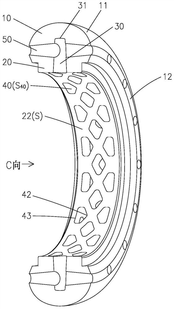
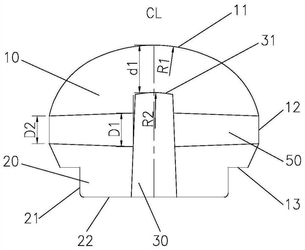
[0032] Refer below Figure 2 to Figure 6 The tire carcass structure of Embodiment 1 of the present invention will be described.
[0033] Such as figure 2 and image 3 As shown, according to the tire carcass structure of the embodiment of the present invention, the carcass includes a head 10 and a neck 20, wherein the head 10 includes a head outer peripheral surface 11, a head side surface 12 and an inner peripheral surface 13 of the head, and the neck The portion 20 includes a neck side surface 21 and an inner peripheral surface 22 of the neck. The inner peripheral surface 22 jointly defines a fitting portion that fits with the rim, and then the head 10 and the neck 20 are designed to be integrated, that is to say, the cross section of the carcass is mushroom-like.
[0034] which, combined with Figure 4 and Figure 5The inner peripheral surface 22 of the neck has several radial central holes 30 and several radial side holes 40 distributed evenly along the entire circumf...
Embodiment 2
[0046] Combine below Figure 7 The tire carcass structure of Example 2 of the present invention will be described.
[0047] According to the tire carcass structure of the embodiment of the present invention, its overall structure and principle are roughly the same as those of Embodiment 1, and the same ones will not be described again. The difference is that in this embodiment, the radial section of the radial central hole 30 It is designed in a cross-like shape. The ratio of the extending width W1 of the radial center hole 30 in the circumferential direction to the extending width W2 of the radial center hole 30 in the axial direction is 103%. Both weight and rigidity have been reduced reasonably to ensure that the tire body has good support performance and cushioning performance.
[0048] Then, the radial cross-section of the radial side hole 40 is designed in a convex shape. The ratio of the extending width W3 of the radial side hole 40 in the circumferential direction t...
PUM
 Abstract
Description
Claims
Application Information
 - R&D
- Intellectual Property
- Life Sciences
- Materials
- Tech Scout
- Unparalleled Data Quality
- Higher Quality Content
- 60% Fewer Hallucinations
Browse by: Latest US Patents, China's latest patents, Technical Efficacy Thesaurus, Application Domain, Technology Topic, Popular Technical Reports.
© 2025 PatSnap. All rights reserved.Legal|Privacy policy|Modern Slavery Act Transparency Statement|Sitemap|About US| Contact US: help@patsnap.com


