Frame stability adjusting device

A technology of adjusting device and stability, applied in the direction of hoisting device, lifting frame, overhead line/cable equipment, etc., can solve the problems of heavy weight of cross arm and trouble in maintenance process, etc.

Active Publication Date: 2021-03-12
PINGYIN POWER SUPPLY CO OF STATE GRID SHANDONG ELECTRIC POWER CO +1
View PDF10 Cites 0 Cited by
  • Summary
  • Abstract
  • Description
  • Claims
  • Application Information

AI Technical Summary

Problems solved by technology

However, the weight of the cross arm is relatively heavy, which brings great troubles to the maintenance process.

Method used


Image

  • Frame stability adjusting device
  • Frame stability adjusting device
  • Frame stability adjusting device

Examples


Embodiment 1

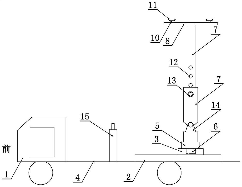
[0028] Embodiment one, such as figure 1 As shown, the invention includes a moving car body 1, a position adjustment component and a height adjustment component. Move the vehicle body 1 to carry the position adjustment component and the height adjustment component to the position where the transformer cross arm needs to be maintained or routinely overhauled. The position adjustment part is installed on the mobile car body 1, and the height adjustment part is installed on the position adjustment part, and can move on the position adjustment part. Specifically, the position adjustment component is installed in the vehicle bucket 4 of the moving vehicle body 1. From the front and rear direction of the mobile vehicle body 1, the position adjustment component is located at the rear of the vehicle, and from the left and right direction, it is located at the center of the vehicle bucket 4. During specific use, the height adjustment component can be moved to the position of the rear o...

Embodiment 2

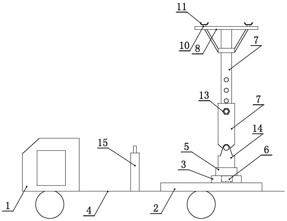
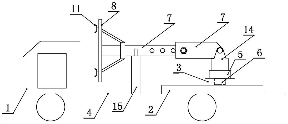
[0039] Embodiment two, such as figure 2 , image 3 As shown, the difference from Embodiment 1 is that the crossbar 8 is connected to the adjustment rod 7 through oblique supports and bearings. The connecting cross bar 8 and the oblique support can rotate axially around the adjusting rod. The crossbar 8 is connected with the adjusting rod through the oblique support and the bearing, and the crossbar 8 and the oblique support can rotate axially around the adjusting rod under manual intervention to realize the angle adjustment of the crossbar 8 and the abutment parts on the crossbar 8.

[0040] By moving the car body 1, the height adjustment component is transported to the position of the frame body that needs maintenance, the height adjustment component is adjusted along the position adjustment component, and then the quantity and positional relationship of the adjustment rod in the height adjustment component is reasonably adjusted according to the height requirement, to The...


PUM


Abstract

The invention discloses a frame stability adjusting device which comprises a movable vehicle body, a position adjusting component and a height adjusting component. The position adjusting component isinstalled on the movable vehicle body, the height adjusting component is installed on the position adjusting component and can move on the position adjusting component, and an abutting component usedfor abutting against a cross arm is installed at the top of the height adjusting component. The height adjusting component is conveyed to the position of a frame needing to be maintained through the movable vehicle body, the position of the height adjusting component is adjusted along the position adjusting component, then the number and the position relation of adjusting rods in the height adjusting component are reasonably adjusted according to the height requirement till the abutting component at the top of the height adjusting component is aligned with the cross arm, then the specific position of the abutting component is adjusted through ascending and descending of a jack till the abutting component abuts against the downwards-inclined end of the cross arm or the whole downwards-moving cross arm, and then the cross arm is fixed again by tightening bolts.

Description

technical field [0001] The invention relates to the technical field of power supply auxiliary equipment, in particular to a frame stability adjusting device. Background technique [0002] For the use of distribution transformers, most of the transformers used in urban areas are rack transformers with cross arms. However, there is a problem of loosening of the bolts used to fasten the cross-arm during the use of the stand-type transformer. Loosening of the bolts will cause the cross-arm to tilt and fall, or the entire cross-arm will be displaced downward, and there is also the problem of displacement of the rod body. The existence of the above-mentioned problems may cause safety problems, and also affect the reliability and use of the power supply system. [0003] And for the maintenance process of cross arm, existing mode generally is to adopt maintenance worker to climb on the rod body, manually lifts the inclined or fallen cross arm, then fastening bolt is tightened and f...

Claims


Application Information

Patent Timeline
IPC IPC(8): B66F7/12B66F7/28H02G1/02E04H12/00E04H12/24
CPCB66F7/12B66F7/28H02G1/02E04H12/24E04H12/00
Inventor 邱茂光房斌侯磊陈磊魏文峰张文
Owner PINGYIN POWER SUPPLY CO OF STATE GRID SHANDONG ELECTRIC POWER CO
Why Eureka
Try Eureka