Flue gas purification system and purification method

A flue gas purification system and flue gas purification technology, applied in the field of flue gas purification, can solve the problems of affecting the exhaust effect, large filter screen resistance, low filtering efficiency, etc.

Pending Publication Date: 2021-03-12
VATTI CORP LTD
View PDF0 Cites 0 Cited by
  • Summary
  • Abstract
  • Description
  • Claims
  • Application Information

AI Technical Summary

Problems solved by technology

[0003] In order to purify the fume discharged from the public flue, a filter device is generally installed in the public flue. The existing filter device has low filtration efficiency and large filter resistance, which affects the smoke exhaust effect.

Method used


Image

  • Flue gas purification system and purification method
  • Flue gas purification system and purification method
  • Flue gas purification system and purification method

Examples


Embodiment 1

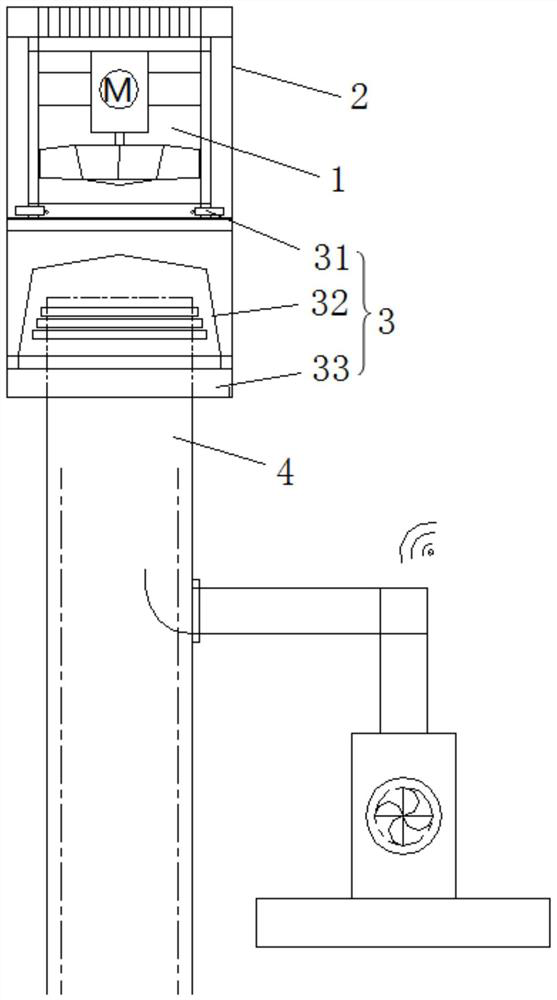
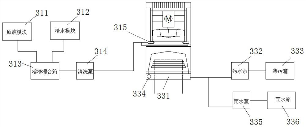
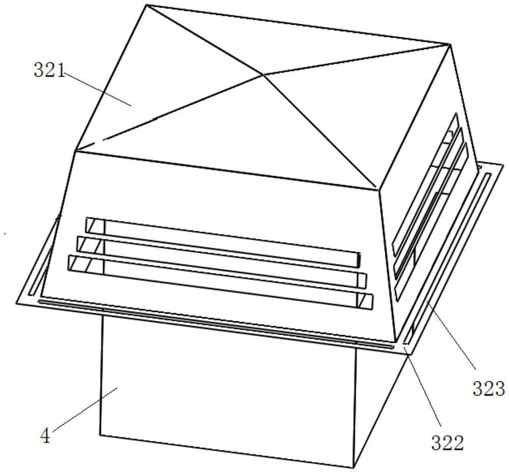
[0041] Embodiment 1 of the present invention provides a flue gas purification system for purifying the flue gas discharged from the smoke exhaust system, such as figure 1 As shown, it includes a fan 1, a protective cover assembly 2, a purification assembly 3, a flue extension pipe 4 and a control assembly 5. Above the assembly 3, the lower end of the flue extension pipe 4 is connected to the flue of the smoke exhaust system, and the upper end is connected to the purification assembly 3; the control assembly 5 is connected to both the fan 1 and the purification assembly 3; the control assembly 5 obtains The number of range hoods in working condition, according to which the concentration of the cleaning liquid in the purification assembly 3 is controlled to purify the flue gas discharged from the flue extension pipe 4;

[0042] Specifically, the upper surface of the protective cover assembly 2 is made of a protective net;

[0043] In this way, with the above structure, the flue...

Embodiment 2

[0078] Embodiment 2 of the present invention provides a flue gas purification method, which uses the flue gas purification system described in Embodiment 1, such as Figure 7 As shown, it specifically includes the following steps:

[0079] S1, the control component acquires the number of range hoods in working state;

[0080] S2, the control component adjusts the concentration of the cleaning liquid in the purification component according to the quantity in S1, and the purification component realizes the purification of the flue gas through the cleaning liquid of this concentration.

[0081] In this embodiment, the cleaning liquid is used to purify the flue gas. Compared with the traditional method of purifying through a filter, the flue gas will not be hindered, so the smoke exhaust effect will not be affected; moreover, the concentration of the cleaning liquid in this embodiment also follows the The number of range hoods in working condition is adjusted, which is targeted. ...


PUM


Abstract

The invention discloses a flue gas purification system and purification method.The flue gas purification system comprises a draught fan, a protective outer cover assembly, a purification assembly, a flue extension pipe and a control assembly. The draught fan and the purification assembly are both arranged in the protective outer cover assembly, and the draught fan is located above the purificationassembly. The lower end of the flue extension pipe is connected with a flue of a flue gas exhaust system, and the upper end of the flue extension pipe is connected with the purification assembly. Thecontrol assembly is connected with the draught fan and the purification assembly. The control assembly obtains the number of extractor hoods in the working state and controls the concentration of cleaning liquid in the purification assembly according to the number so as to purify flue gas exhausted from the flue extension pipe. The cleaning liquid is used for purifying flue gas, and compared withtraditional purification through a filter screen, the flue gas is not hindered, so that the flue gas exhaust effect is not affected; and in addition, the concentration of the cleaning liquid is adjusted according to the number of the extractor hoods in the working state, and pertinence is achieved.

Description

technical field [0001] The invention belongs to the technical field of flue gas purification, and in particular relates to a flue gas purification system and a purification method. Background technique [0002] The outlet of public flue in high-rise is generally set at the top of the floor. In order to ensure that the range hoods of users on each floor can exhaust smoke smoothly, a flue fan is generally installed at the exit of the public flue. Negative pressure is formed at the outlet of the flue, and the range hoods on the user side are also equipped with fans, so that the oil fume on the user side can be smoothly discharged through the public flue. [0003] In order to purify the oil fumes discharged from the public flue, filter devices are generally installed in the public flue. The existing filter devices have low filtration efficiency and large filter screen resistance, which affects the smoke exhaust effect. Contents of the invention [0004] In order to solve the ...

Claims


Application Information

Patent Timeline
Patent Type & Authority Applications(China)
IPC IPC(8): F24C15/20B01D47/06
CPCB01D47/06F24C15/2021F24C15/2035F24C15/2057
Inventor 余丹阳王智捷李永波姚家前潘叶江
Owner VATTI CORP LTD
Why Eureka
Try Eureka