Motor train unit pantograph working mode test device

A technology of working mode and test device, applied in the field of working mode test device of EMU pantograph, can solve the problems such as easy loss of force and sudden drop, increase in size of test device, high cost of insulator, etc., so as to reduce test expenses. , saving test time and low cost

Pending Publication Date: 2021-03-12
DALIAN JIAOTONG UNIVERSITY
View PDF0 Cites 0 Cited by
  • Summary
  • Abstract
  • Description
  • Claims
  • Application Information

AI Technical Summary

Problems solved by technology

[0003] The entire structure of the pantograph is mainly fastened to the roof of the EMU by three ceramic insulators on the base. The main problems in the working modal test include: First, the insulators are expensive and heavy and difficult to take directly The test will increase the cost of the test; secondly, during the actual operation of the train, the pantograph will have different lifting heights when passing through different road sections, so the pantograph will also have three different heights during the working modal test. However, it is difficult to maintain the pantograph stably by manpower or simple mechanical devices, and it is easy to lose the force and suddenly fall, which increases the risk. Moreover, it is difficult to measure the height of the pantograph with traditional tools such as meters. And the accuracy is not enough; third, the pantograph head is in contact with the catenary to transmit current, the cable of the catenary will have a downward pressure on the pantograph head, and for different heights of the pantograph, The height of the catenary also needs to be changed in time, which increases the volume of the test device in vain

Method used


Image

  • Motor train unit pantograph working mode test device
  • Motor train unit pantograph working mode test device
  • Motor train unit pantograph working mode test device

Examples


Embodiment 1

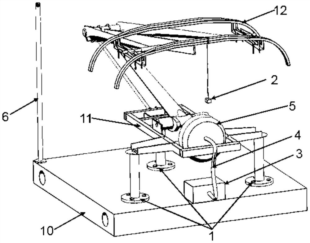
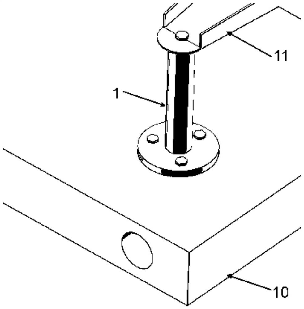
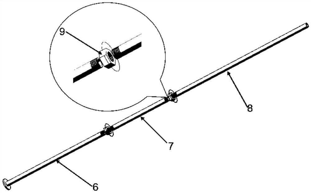
[0039] Such as Figure 1-5 As shown, the present invention provides a pantograph operating mode test device for EMUs, including: pantograph and experimental device, characterized in that the experimental device includes: supporting structure, driving structure, measuring structure and weight structure, the support structure includes a support base 10 and a support column 1, the support column 1 is set on the support base, the pantograph is set on the support column 1, and the support column 1 includes to support Column I, supporting column II and supporting column III, the supporting column I, the supporting column II and the supporting column III are arranged in a triangle, the supporting column I, the supporting column II and the supporting column Column III is connected to the pantograph base 11 through bolts, the structures of the supporting column I, the supporting column II and the supporting column III are the same, and the supporting column I is a circular tube structu...


PUM


Abstract

The invention provides a motor train unit pantograph working mode test device which comprises a pantograph and an experiment device, the experiment device comprises a supporting structure, a driving structure, a measuring structure and a weight structure, the supporting structure comprises a supporting base and a supporting column, the supporting column is arranged on the supporting base, and thepantograph is arranged on the supporting column; the driving structure is an air bag structure, and the air bag structure is arranged in front of a pantograph truss of the pantograph; the measuring structure is a measuring pipe, and the measuring pipe is arranged on the supporting base; and the weight structure is a weight, and the weight is arranged at the pantograph head of the pantograph. The pantograph is erected to drive the pantograph through the air bag, and therefore on the premise that experiment requirements are met, the size is smaller, precision is higher, and experiment steps aresimpler and more labor-saving.

Description

technical field [0001] The invention relates to the technical field of pantograph testing, in particular to a working mode test device for a pantograph of an EMU. Background technique [0002] During the operation of high-speed trains, pantograph-catenary failures occur from time to time, many of which are caused by the excessive amplitude of pantograph and catenary during train operation. When the train is running, the resonance will increase the amplitude of the pantograph and the catenary, resulting in the separation of the pantograph and catenary, which will lead to the deterioration of the current receiving quality. The severe vibration of the pantograph and catenary will also damage the pantograph and catenary, and even cause drilling accidents. During the design and operation of the pantograph-catenary system, pantograph-catenary resonance should be avoided as much as possible. Therefore, it is very important to obtain the natural frequency of the pantograph and the ...

Claims


Application Information

Patent Timeline
Patent Type & Authority Applications(China)
IPC IPC(8): G01M7/02G01M7/08
CPCG01M7/02G01M7/027G01M7/08
Inventor 马思群徐笑莹孙雅琪王涛李旭洋
Owner DALIAN JIAOTONG UNIVERSITY
Why Eureka
Try Eureka