
Line fault detection method and device

A technology for detecting device and line faults, applied to measuring devices, cleaning methods using liquids, cleaning methods using gas flow, etc., can solve problems such as the inability to determine the cause of an optical fiber line break

Inactive Publication Date: 2021-03-12
马鞍山黑火信息科技有限公司
View PDF0 Cites 2 Cited by
  • Summary
  • Abstract
  • Description
  • Claims
  • Application Information

AI Technical Summary

Problems solved by technology

[0004] The purpose of the present invention is to provide a method and device for line fault detection, which is used to solve the problem that the existing line fault detection device can only detect whether the optical fiber line is on or off, but cannot judge the cause of the optical fiber line disconnection

Method used


Image

  • Line fault detection method and device
  • Line fault detection method and device
  • Line fault detection method and device

Examples


Embodiment Construction

[0040] The technical solutions of the present invention will be clearly and completely described below in conjunction with the embodiments. Apparently, the described embodiments are only some of the embodiments of the present invention, not all of them. Based on the embodiments of the present invention, all other embodiments obtained by persons of ordinary skill in the art without creative efforts fall within the protection scope of the present invention.

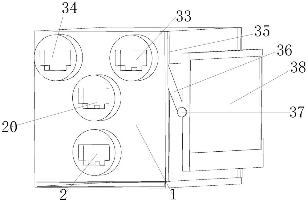
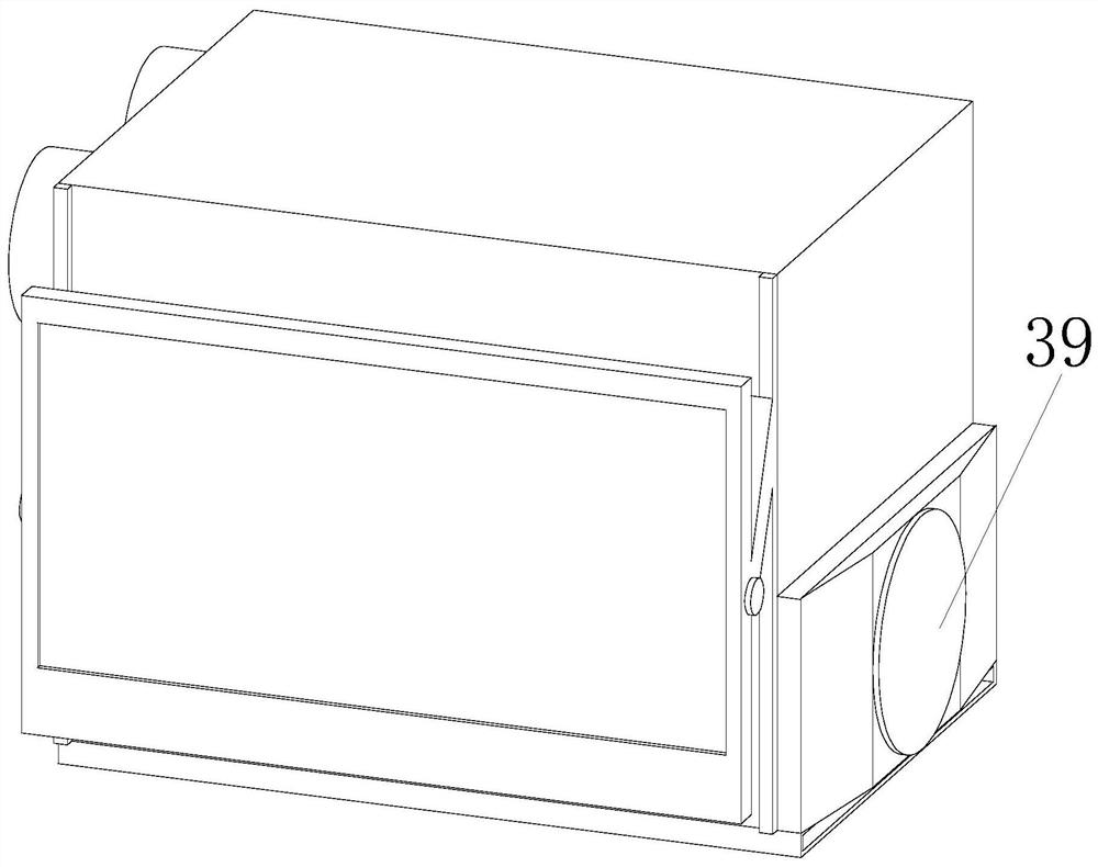
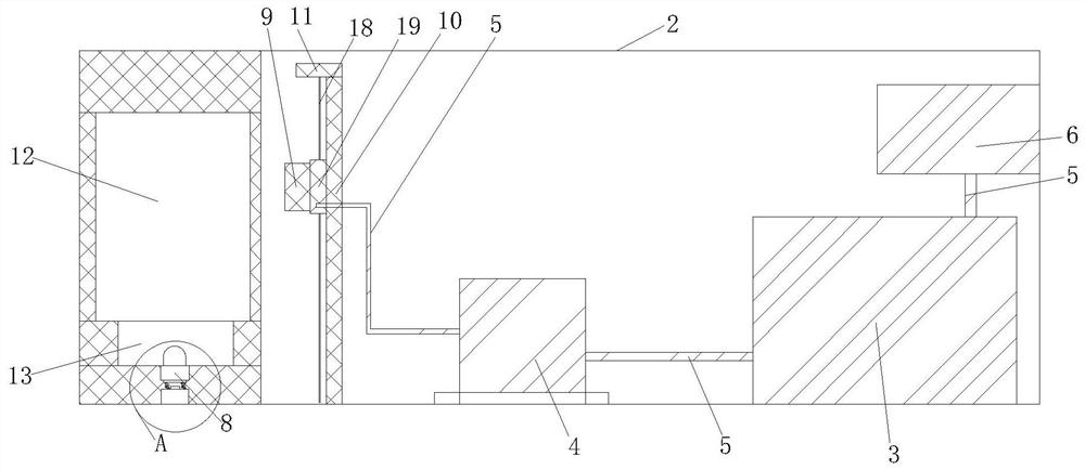
[0041] Such as Figure 1-6 As shown, a device for line fault detection includes a detection box 1, and the detection box 1 includes an ion dust removal assembly, an optical fiber cleaning assembly, an optical fiber testing assembly, a display assembly, and a heat dissipation assembly;

[0042] The ionization dust removal assembly includes the ion dust removal casing 2, the gas storage tank 3, the supercharger 4, the air pipe 5, the compressor 6, the optical fiber socket 7, the sensor switch 8, the ion air knife 9, the air k...


PUM


Abstract

The invention discloses a line fault detection method and device, which are used for solving the problem that the existing line fault detection device can only detect whether an optical fiber line isconnected or disconnected and cannot judge the reason causing the optical fiber line disconnection. Through the arrangement of the ion air knife and the first lead screw motor, when it is detected that the optical fiber crystal head is inserted into the optical fiber socket, the crystal head elastic piece presses the induction switch, the ion air knife blows out high-pressure airflow with currentelectrons, the high-pressure airflow enables tiny attachments attached to the crystal head to be blown out of the optical fiber crystal head, and the purpose of cleaning the optical fiber crystal headis achieved. Meanwhile, a first lead screw motor drives an ion air knife to blow air up and down at a constant speed, so that tiny attachments adhered to the crystal head are further blown out of theoptical fiber crystal head, and the problem that an existing line fault detection device does not have the function of cleaning electrified tiny attachments is solved; and through the arrangement ofthe sprayer and the rotating plate, the sprayer sprays a cleaning agent stored in the high-pressure water tank onto the crystal head, and stains attached to the crystal head are flushed.

Description

technical field [0001] The invention belongs to the field of optical fiber inspection, relates to an optical fiber line fault detection technology, and specifically relates to a line fault detection method and device. Background technique [0002] The tiny fiber is encapsulated in a plastic sheath that allows it to be bent without breaking. Typically, a transmitting device at one end of the fiber uses light emitting diodes and / or a laser to transmit pulses of light into the fiber, and a receiving device at the other end of the fiber uses a photosensitive element to detect the pulses. [0003] During the manufacturing process, optical fibers can become contaminated and / or damaged. For example, optical fibers may chip, crack or splinter during the cleaving process. Other processes, such as stripping, cleaning, etc., can leave particulate or fluid contamination on the fibers. Such damage and / or contamination can degrade the signal quality of optical signals transmitted over ...

Claims


Application Information

Patent Timeline
IPC IPC(8): G01N21/01B08B3/02B08B5/02B08B7/00G01M11/02G01N21/84
CPCB08B3/02B08B5/02B08B7/00G01M11/0207G01M11/0285G01N21/01G01N21/84
Inventor 汪正曹艳刘晓梅叶铭
Owner 马鞍山黑火信息科技有限公司
Learn More