Anti-wear stranding device for electric wire production line

A wear-resistant, production-line technology that can be used in circuits, electrical components, cable/conductor manufacturing, etc., to solve problems such as scratched wires, wire abrasion, etc.

Active Publication Date: 2021-03-12
衡阳市捷讯实业有限公司
View PDF7 Cites 10 Cited by
  • Summary
  • Abstract
  • Description
  • Claims
  • Application Information

AI Technical Summary

Problems solved by technology

[0003] However, in order to prevent the wires from being separated from the wire mechanism in the existing twisting device, the wire mechanism mainly uses a wire loop, a wire tube, or a wire hole on the support plate to carry out wires, resulting in serious wear and tear on the wires, and even scratches on the wires.

Method used


Image

  • Anti-wear stranding device for electric wire production line
  • Anti-wear stranding device for electric wire production line
  • Anti-wear stranding device for electric wire production line

Examples


Embodiment 1

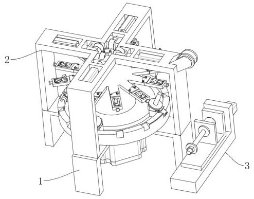
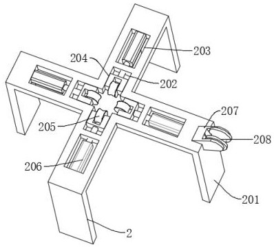
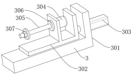
[0034] like Figure 1-7 As shown, a wear-resistant twisting device used in a wire production line includes a winding mechanism 3, a twisting mechanism 1 and a guiding mechanism 2, and the twisting mechanism 1 includes a support frame 101, a driving motor 102, and a turntable 103 , annular chute 104, fixed assembly 105, column 106, support plate 107, the bottom center of support frame 101 is connected with drive motor 102 by bolt, the output end of drive motor 102 passes support frame 101, and stretches into turntable 103 insides, And it is connected with the turntable 103 by a key, the top of the turntable 103 is provided with an annular chute 104 and several draw-in grooves, the draw-in groove is positioned at the outer side of the annular chute 104, and the inner side of the annular chute 104 is slidably connected with a fixed assembly 105, and the turntable 103 The center of the top is welded with a column 106, and the outer top of the column 106 is connected with several s...

Embodiment 2

[0037] like Figure 8 As shown, the difference between embodiment 2 and embodiment 1 is that the driving structure includes slider three 504 and cylinder two 51, slider three 504 is slidably connected to the inner side of chute two 502, and slider three 504 is close to the fixed guide wheel 503 One end of one end is provided with the installation slot that is used to install the moving guide wheel 506, and the end of the slider three 504 away from the fixed guide wheel 503 is connected to the output end of the cylinder two 51 by bolts, and the fixed end of the cylinder two 51 is connected to the outside of the fixed frame 501 by bolts , such arrangement can drive slide block three 504 to move by cylinder two 51, and slide block three 504 drives moving lead wheel 506 to move, and electric wire is extruded between moving lead wheel 506 and fixed lead wheel 503, prevents electric wire from swinging.

[0038]In the above structure, when in use, first place an appropriate number of...


PUM


Abstract

The invention discloses an anti-wear stranding device for an electric wire production line, the anti-wear stranding device comprises a winding mechanism, a stranding mechanism and a guide mechanism, the stranding mechanism comprises a support frame, a driving motor, a rotating table, an annular sliding groove, a fixing assembly, a stand column and a support plate, and the center of the bottom of the support frame is connected with the driving motor through a bolt; the output end of the driving motor penetrates through the support frame, stretches into the inner side of the rotating table and is connected with the rotating table through a key, the annular sliding groove and a plurality of clamping grooves are formed in the top of the rotating table, the clamping grooves are located in the outer side of the annular sliding groove, and the fixing assembly is connected to the inner side of the annular sliding groove in a sliding mode. Through the arrangement of the rotating structure and the wire guide assembly, the electric wire is prevented from being separated from the fixed wire guide wheel, and meanwhile, the problem that the electric wire is abraded before being stranded is solved due to rolling connection between the fixed wire guide wheel and the electric wire; and the guide mechanism is arranged, so that the problem that the electric wire is abraded after being stranded issolved.

Description

technical field [0001] The invention relates to the technical field of twisting devices, in particular to an anti-wear twisting device for wire production lines. Background technique [0002] Wires and cables are used to transmit electric (magnetic) energy, information and wire products that realize the conversion of electromagnetic energy. In a broad sense, wires and cables are also referred to as cables for short. In a narrow sense, cables refer to insulated cables, which can be defined as: a collection composed of the following parts ; One or more insulated wire cores, and their respective possible covering layers, total protective layer and outer sheath, and the cable may also have additional uninsulated conductors. Wire products used to transmit electric (magnetic) energy, information and realize the conversion of electromagnetic energy. The twisted wire is realized by twisting a single wire around the twisted wire shaft at an equal angular velocity and moving the twist...

Claims


Application Information

Patent Timeline
Patent Type & Authority Applications(China)
IPC IPC(8): H01B13/02
CPCH01B13/0207
Inventor 陈文
Owner 衡阳市捷讯实业有限公司
Why Eureka
Try Eureka